


66
Radiance Direct Vent/Natural Vent Gas Heater
20004188
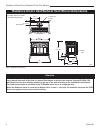
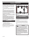
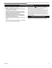
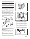
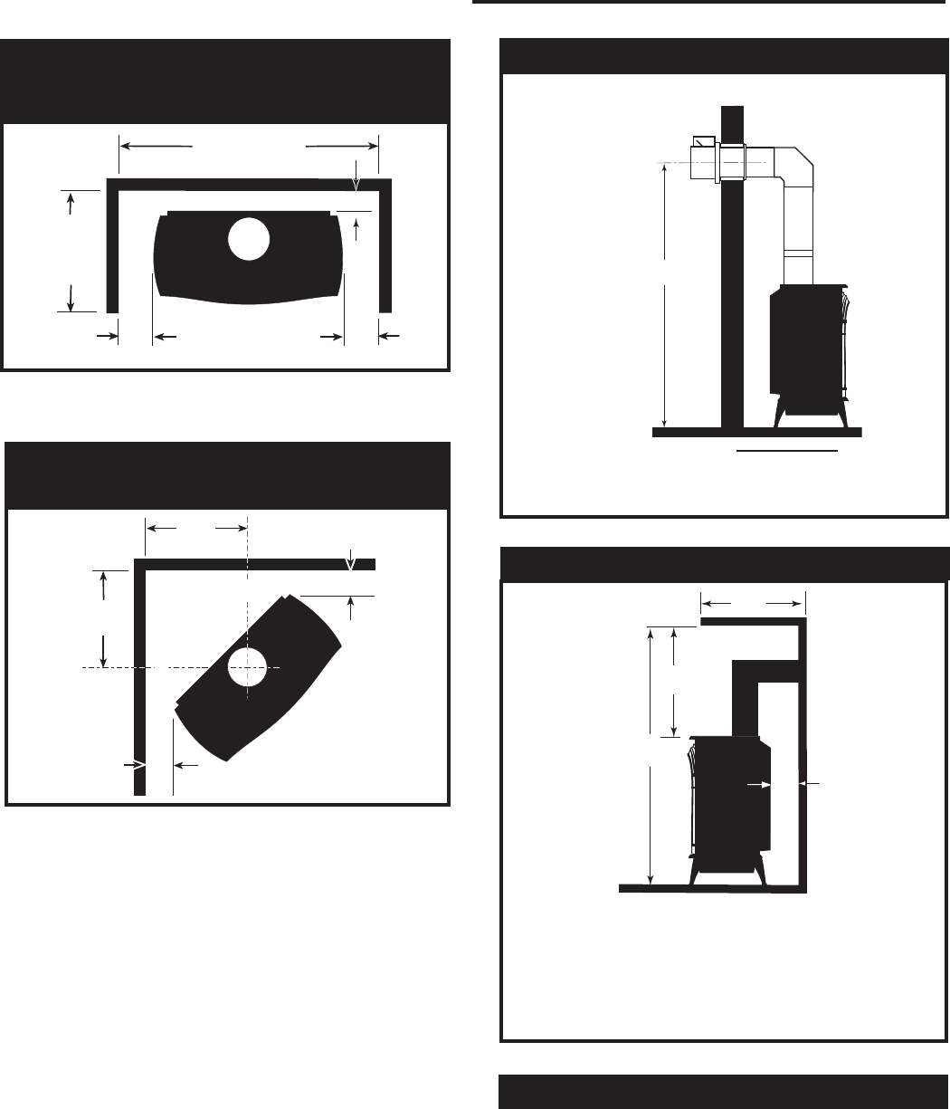
Parallel Installation: Minimum Clearance
and Flue Centerline, Direct Vent and Natu
-
ral Vent
Fig. 3 Parallel installation, minimum back and side clear-
ances, and flue centerlines.
ST130
42" (1070mm)
Min. Alcove Width
48"
(1220mm)
Max. Alcove
Depth
6"
(150mm)
6"
(150mm)
4" (102mm)
ST129
18"
(457mm)
18"
(457mm)
6"
(150mm)
6"
(150mm)
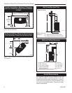
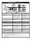
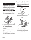
Corner Installation: Minimum Clearance and
Flue Centerline, Direct Vent & Natural Vent
Fig. 4 Corner installation, minimum corner clearances and
flue centerline.
Wall Centerline from Floor
ST131b
Stardance
wall thimble
9/28/00 djt
A
A
Effective Minimum
Centerline 57” (1448 mm)
(CFM Corporation Pipe)
55” (1399 mm) (Simpson DuraVent Pipe)
ST131b
Fig. 5 Minimum wall centerline.
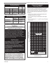
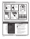
Direct Vent Only
Hearth Requirements
The Radiance Heaters must be installed on rigid floor-
ing. When the heater is installed directly on any com-
bustible surface other than wood flooring, a metal or
wood panel extending the full width and depth of the
unit must be used as the hearth. There are no other
hearth requirements.
* needed for installing DuraVent Minimum Vent Kit #2792 or
CFM Corporation Minimum Vent Kit #7TFSMSK.
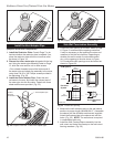
A
C
D
ST101b
Stardance
Direct Vent
Min. Clrnc
9/28/00 djt
B
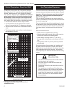
A: Rear Wall 4” (102 mm)
B: Min. Clearance 44” (1118 mm)*
C: Min. Alcove Height 72” (1830 mm)*
D: Max. Alcove Depth 48” (1220 mm)
Sidewall Clearance 6” (150 mm)
ST101b
Fig. 6 Dimensions and clearances to ceiling or alcove.
Direct Vent Only
Wall and Ceiling Clearances