


3030
Radiance Direct Vent/Natural Vent Gas Heater
20004188
ST667
RNVOD
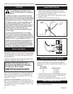
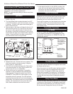
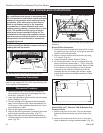
air shutter
converting
from NG to Lp
6/4/01 djt
Burner
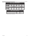
Refer to Table 2
ST667
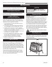
Fig. 54 Adjust air shutter according to Table 2.
Conversion Precautions
Before proceeding, turn control knob on valve to OFF
and turn gas supply OFF. Turn OFF any electricity that
may be going to the appliance.
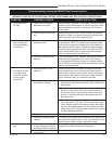
Burner Orifice Conversion
1. Hold the burner at the right hand side and lift to clear
the right burner leg. Then pull to the right to clear the
injectors on the left hand side.
2. Remove injector orifices from left burner leg using
1/2” wrench. (Fig. 61)
3. Install conversion orifices. (Refer to Table 1)
4. Air shutter adjustment. The unit is shipped from the
factory with the air shutter open 1”. For LP units only,
the air shutter could be closed further. Refer to Table
2 for minimum air shutter opening. The air shutter
is located on the bottom of the burner to the left.
Unfasten the two nuts holding the shutter in place.
Adjust the air shutter as needed according to Table
2. (Fig. 54)
Fuel Conversion Instructions
WARNING! This conversion kit shall be installed
by a qualified service agency in accordance with
the manufacturer’s instructions and all applicable
codes and requirements of the authority having
jurisdiction. If the information in these instruc-
tions is not followed exactly, a fire, explosion
or production of carbon monoxide may result
causing property damage, personal injury or loss
of life. The qualified service agency is respon-
sible for the proper installation of this kit. The
installation is not proper and complete until the
operation of the converted appliance is checked
as specified in the manufacturer’s instructions
supplied with the kit.
CAUTION: The gas supply shall be shut off prior
to disconnecting the electrical power, before pro-
ceeding with the conversion.
ST226
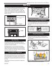
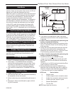
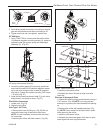
attach gas line
12/8/99 djt
PILO
T
O
N
O
F
F
PILO
T
AD
J
L
O
H
I
Main
Gas Line
Gas Supply Inlet
ST226
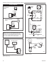
Fig. 52 Attach the gas line to the left side of the valve.
ST350
Jefferson
air shutter adj
3/20/00 djt
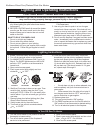
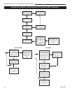
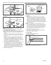
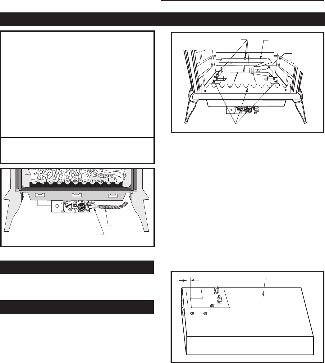
Remove Screws
Rear Log Bracket
Pilot
Left & Right Log
Bracket Assembly
ST350
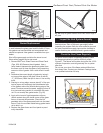
Fig. 53 Remove rear log bracket and left and right log bracket
assembly.
Conversion Procedure
1. Remove stove front. Lift stove front up and then
swing bottom out and away to disengage from the
stove body. (Page 32, Fig. 62)
2. Undo the right and left latches at the top of the glass
frame. (Page 32, Fig. 63)
3. Pull the top edge of the glass and frame assembly
away from the firebox face. Place the assembly out
of the way on a flat, padded surface such as a coun-
ter protected by a towel.
4. Remove the logset from the firebox.
5. Remove the rear log bracket by loosening the screw
and lifting the bracket up and away. (Fig. 53)
6. Remove the right and left log bracket assembly by
unfastening the two screws which hold the burner in
place. (Fig. 53)
Models 3350, 3351, 3360 thru 3369 (R Models) Only
Honeywell Valve
1. Remove cap from Hi-Lo knob. This can be accom-
plished by lifting the plastic cap off the screw. (Fig.
55)
2. Remove the screw from center of Hi-Lo knob with
small screwdriver turning counterclockwise. (Fig. 55)