


2222
Radiance Direct Vent/Natural Vent Gas Heater
20004188
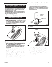
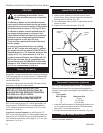
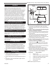
Thermostat Connection (optional)
Use only a thermostat rated for 500 - 750 millivolts.
Check the table below for the appropriate gauge ther-
mostat wire to use for the length of lead required in your
installation.
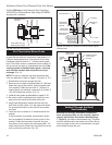
1. Install the wall thermostat in the desired location and
run the wires to the stove location. Terminate these
leads with 1/4” female connectors.
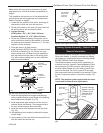
2. Connect the thermostat wires to the valve. (Fig. 43)
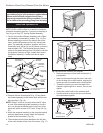
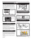
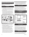
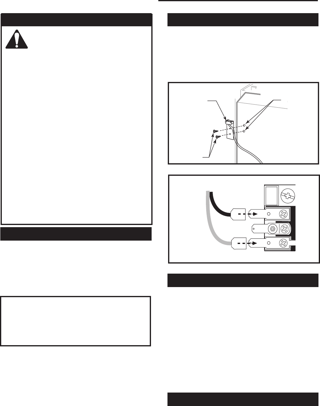
Install ON/OFF Switch
The switch assembly parts are found in the parts bag.
1. Attach switch assembly to left rear side of stove
shroud (when facing shroud) using two screws and
existing holes in shroud. (Fig. 42)
2. Run wires down back of stove, under bottom of rear
shroud to valve.
3. Attach wires to valve terminals. (Fig. 43)
PILOT
ADJ
TP
TH
TPTH
ST228
attach switch
wires to valve
12/99
ST228
Fig. 43 Attach switch wires to valve.
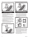
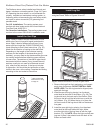
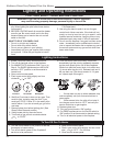
Install the Mesh and Grille
Place the mesh and grille on the top of the Radiance
stove to complete assembly.
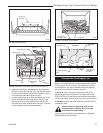
Burner Information
The appliance must only use the gas specified on the
rating plate, unless converted using a Vermont Castings
Fuel Conversion Kit. To convert from LP to Natural Gas
use Kit #000-5009. To convert from Natural Gas to LP
use Kit #000-5010.
Conversion instructions are provided with each kit and
beginning on Page 29 in this manual.
THIS APPLIANCE SHOULD BE CON-
NECTED TO THE GAS SUPPLY ONLY BY
A QUALIFIED GAS SERVICE TECHNICIAN.
FOLLOW ALL LOCAL CODES.
THERE MUST BE A GAS SHUT-OFF BE
-
TWEEN THE STOVE AND THE SUPPLY.
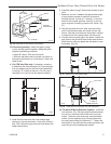
In order to connect Natural Gas, use a fitting with 1/2”
NPT on the valve side and 1/2” natural gas supply line
with an input of 35,000 BTUs at a manifold pressure
of 3.5” between minimum inlet supply of 5.5” w.c. and
maximum of 14.0” w.c.
In order to connect Propane, use a fitting with 1/2”
NPT on the valve side and 1/2” propane gas supply line
with an input of 35,000 BTUs at a manifold pressure of
10.0” between a minimum inlet supply of 11.0” w.c. and
maximum of 14.0” w.c.
This appliance should only be connected
by a qualified gas technician. Test to
confirm manifold pressures as specified
below.
The Radiance Heater and its individual shutoff
valve must be disconnected from the gas supply
piping during any pressure testing of that system
at test pressures in excess of 1/2 psig (3.5 kPa).
The Radiance Heater must be isolated from the
gas supply piping system by closing its indi-
vidual manual shutoff valve during any pressure
testing of the gas supply piping system at test
pressure equal to or less than 1/2 psig.
There must be a gas shutoff between the stove
and the supply.
In order to connect Natural Gas, use a fitting
with 1/2” NPT on the valve side and 1/2” natural
gas supply line with an input of 35,000 BTUs at a
manifold pressure of 3.5” between minimum inlet
supply of 5.5” w.c. and maximum of 14.0” w.c.
In order to connect Propane, use a fitting with 1/2”
NPT on the valve side and 1/2” propane gas sup
-
ply line with an input of 35,000 BTUs at a manifold
pressure of 10.0” between a minimum inlet supply
of 11.0” w.c. and maximum of 14.0” w.c.
CAUTION
ST315
attach switch assy
1/31/00 djt
Switch As-
sembly
Screws
Existing
Holes
ST315
Fig. 42 Attach switch assembly to rear shroud.
Thermostat
Wire / Gauge Maximum Run
18 20 feet
16 20 - 40 feet
14 up to 60 feet