


11
Dutchwest
7001219
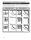
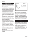
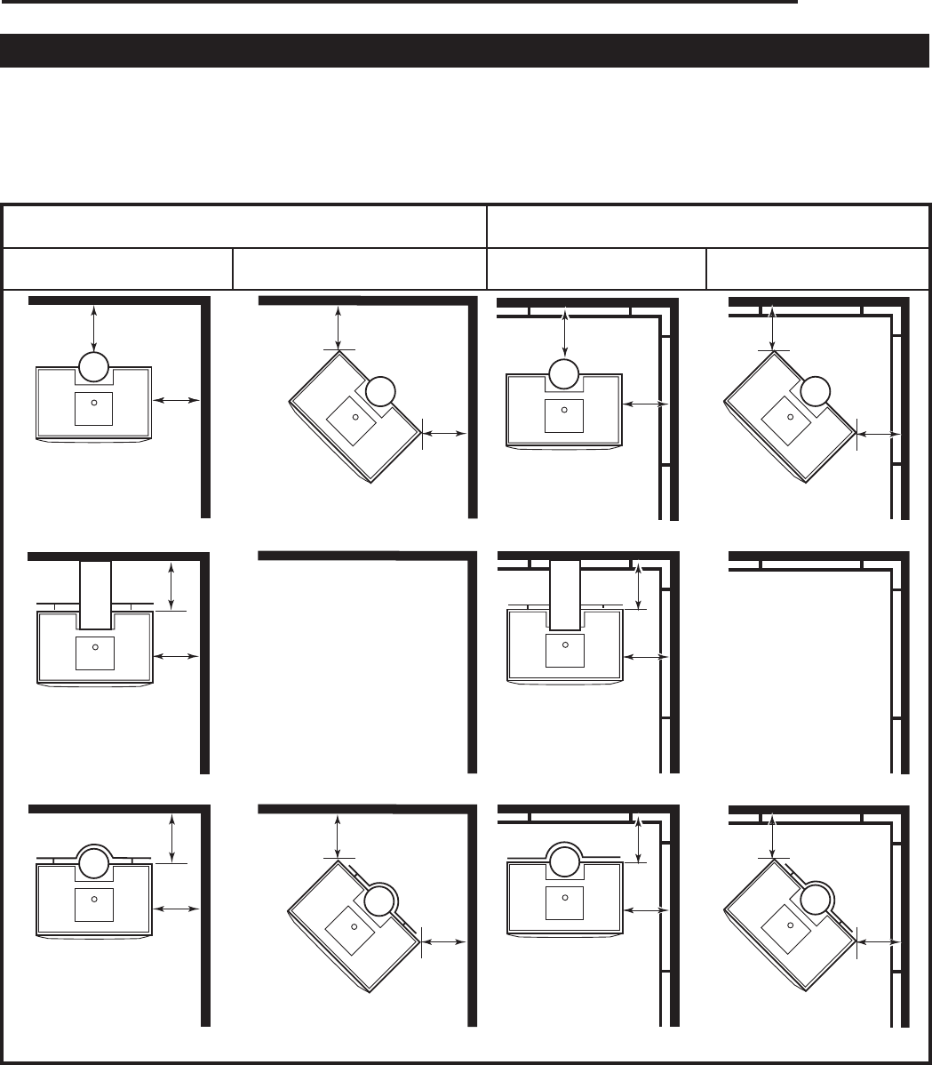
Clearance Chart Reference Diagrams
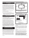
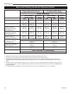
Refer to the diagrams below when using the Stove and Chimney Connector Clearance Chart which follows. For ex-
ample, the letter “A” gives the minimum side clearance for installations in which the stove is not equipped with a rear
heat shield and the wall beside the stove is not protected. “D” gives the minimum side clearance when the stove does
not have a rear heat shield, but the wall is protected.
Measure clearance distances from the top plate of the stove or chimney connector to the wall, not the wall protector.
ST255a
exit diagram
6/30/00 djt
Unprotected Surfaces Protected Surfaces
Parallel Installations Corner Installations Parallel Installations Corner Installations
Installations with no stove heat shields
Rear exit, rear heat shield installations
Top exit, rear heat shield and chimney connector heat shields or double wall connector
A
B
C
C
H
G N / A
E
D
J
I
N / A
F
F
L
K
M
M
O
N
P
P
ST255a