


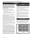
13
Defiant Woodburning Stove
30001693
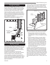
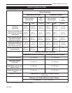
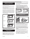
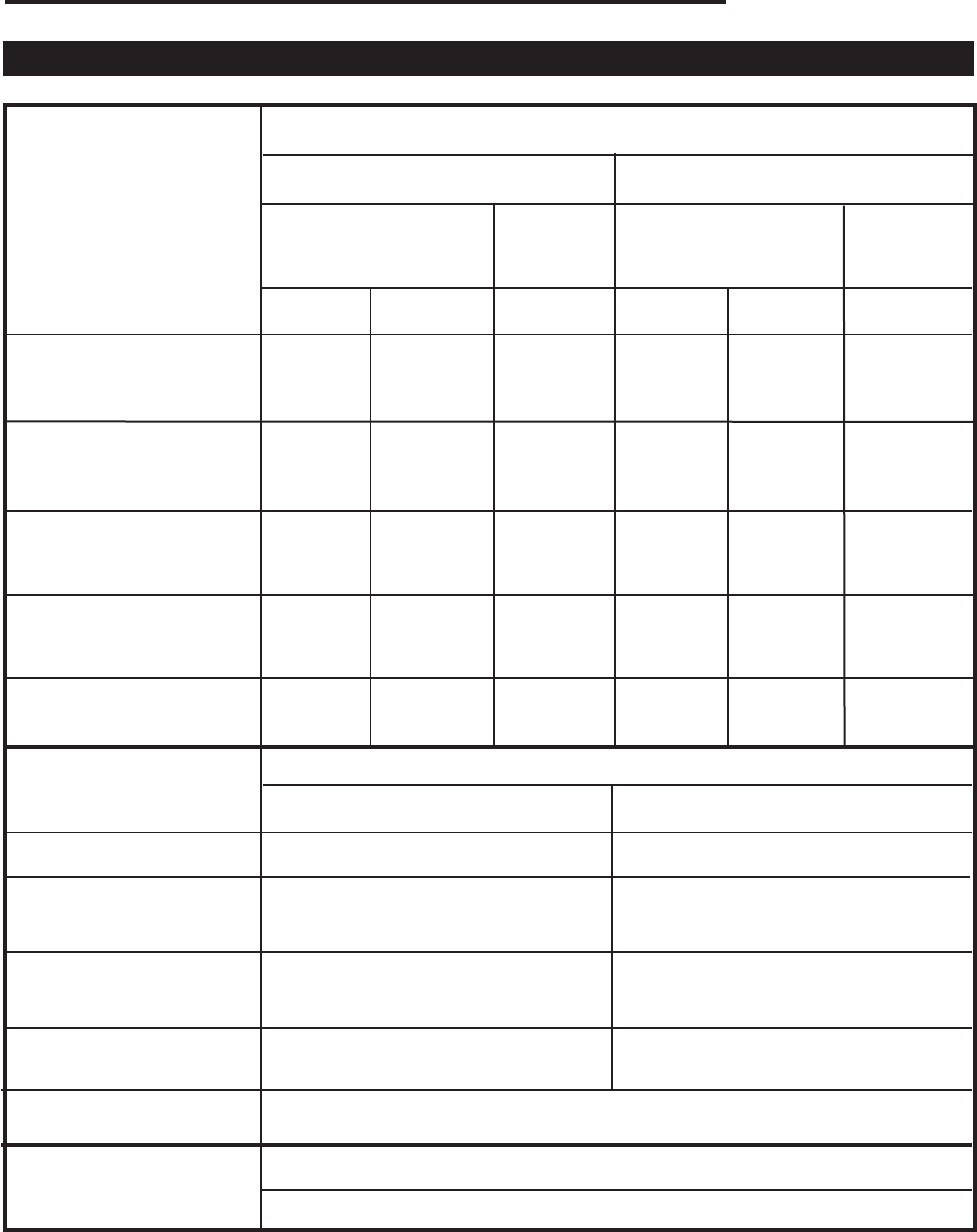
Defiant Clearance Chart
for use with either a 6” or 8” chimney connection
Stove Clearance
Stove Installed
Parallel to Wall
Unprotected Surfaces Protected Surfaces
Side Rear Corners Side Rear Corners
No stove
heat shields
Chimney Connector Clearance
Unprotected Vertical Surfaces Protected Vertical Surfaces
Single-wall connector
Single-wall connector;
rear heat shield on
stove only
Clearance to Combustibles in Front of Stove
48” (1220 mm)
30” (760 mm) 25” (635 mm)
18” (460 mm) 14” (355 mm)
All Installations
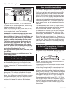
Stove Installed
Parallel to Wall
Stove
in
Corner
Stove
in
Corner
Stove, top exit with rear
heat shield, no connector
heat shields
Single-wall connector
with shields, and rear heat
shield on stove
Double-wall chimney con-
nector
(A) 24” (B) 33” (C) 23” (D) 14” (E) 28” (F) 18”
(610 mm) (840 mm) (585 mm) (355 mm) (710 mm) (460 mm)
(M) 24” (N) 17” (O) 17” (P) 14” (Q) 17” (R) 12”
(610 mm) (430 mm) (430 mm) (355 mm) (430 mm) (305 mm)
(G) 24” (H) 21” (I) 17” (J) 14” (K) 17” (L) 12”
(610 mm) (533 mm) (430 mm) (355 mm) (430 mm) (305 mm)
Stove, top exit with rear
heat shield, and double-
wall chimney connector*
Stove, top exit with rear
heat shield, and heat
shields on connector
Unprotected or Protected Ceiling Surfaces
24” (610 mm)
Single-wall connector
14” (355 mm) 14” (355 mm)
14” (355 mm) 12” (305 mm)
* Using a listed double wall oval to round connector.
Stove, rear exit with rear
heat shield only
(Y) 27” (Z) 24” N/A (AA) 17” (BB) 20” N/A
(686 mm) (610 mm) (430 mm) (508 mm)
(S) 24” (T) 17” (U) 17” (V) 14” (W) 15” (X) 12”
(610 mm) (430 mm) (430 mm) (355 mm) (380 mm) (305 mm)