


7
Intrepid 1640 Woodburning Stove
30000830
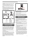
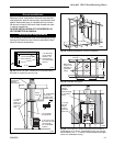
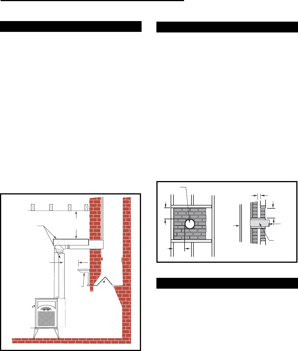
Connection Above the Fireplace
In this installation, the chimney connector enters the
fireplace flue though a thimble located above the
fireplace. The liner of the fireplace chimney should
extend at least to the point at which the chimney
connector enters the chimney. Follow all the guidelines
for installing a chimney connector into a freestanding
masonry chimney, and pay special attention to these
additional points:
• Check the stove and chimney connector clearances
to combustible mantel and trim materials. If neces-
sary, use a combination of mantel, trim, and connec-
tor heat shields to provide the required clearances.
Refer to Page 12.
• Double-check connector clearance to the ceiling.
• The fireplace damper must be closed and sealed to
prevent room air from being drawn up the flue which
could reduce performance. However, it must be
possible to reopen the damper to inspect or clean
the chimney.
• Floor protection requirements also apply to fireplace
installations. Refer to Page 8.
INTREPID II
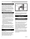
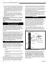
Fig. 7 If the clearance between the chimney connector and
either the ceiling or the mantel is inadequate, a protective
heat shield is required.
Mantel
With Chimney
Connector Heat
Shields
10”
(250 mm)
10”
(250 mm)
ST244a
Wall Pass-throughs
Whenever possible, design the installation so that the
connector does not pass through a combustible wall. If
you must include a wall pass-through in your installa-
tion, check with your building inspector before you
begin. Also check with the chimney connector manu-
facturer for any specific requirements.
Consult with your dealer regarding special connection
components available for use as wall pass-throughs.
Use only parts that have been tested and listed for use
as a wall pass-through. Refer to Figures 9 - 12 for
further details.
U.S. Requirements:
The National Fire Protection Association (NFPA) has
established guidelines for use in the United States for
passing chimney connectors through combustible walls.
Many building code inspectors follow these guidelines.
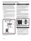
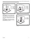
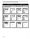
Figure 9 shows one NFPA-approved method. All
combustible material in the wall is cut away to provide
12" (305mm) clearance to the connector. Brick and
mortar are used to enclose the clearance area.
Min. 2" (51mm) Chimney
clearance to brick and
combustibles
A = Minimum 12" (305 mm) brick
construction between liner and
combustible framing materials
Min. 12"
(305 mm)
Fire clay
liner
A
A
Chimney Flue
Fire clay liner
Masonry
Chimney
constructed
to NFPA
211
Fig. 9 Masonry Wall Pass-through with single wall
chimney connector.
Chimney
connector
ST272
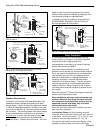
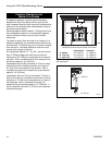
Alternate Methods Approved by the NFPA:
• Using a section of double-wall chimney with a 9"
(229mm) clearance to combustibles. (Fig. 10)
• Placing a chimney connector pipe inside a steel
double-wall ventilated thimble, which is then sepa-
rated from combustibles by 6" (152mm) of fiberglass
insulating material. (Fig. 11)
• Placing a chimney connector pipe inside a section of
9" (229mm) diameter, solid-insulated, factory-built
chimney, with two inches of air space between the
chimney section and combustibles. (Fig. 12)