


13
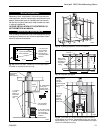
Intrepid 1640 Woodburning Stove
30000830
Alcove Installations
Because of their restricted air flow and heat retention
characteristics, specific construction requirements and
special clearances apply to installations into alcoves.
No stove or chimney connector heat shields are used
in alcove installations.
ALCOVE INSTALLATION OF THE INTREPID II IS
NOT PERMITTED IN CANADA.
Construction Requirements
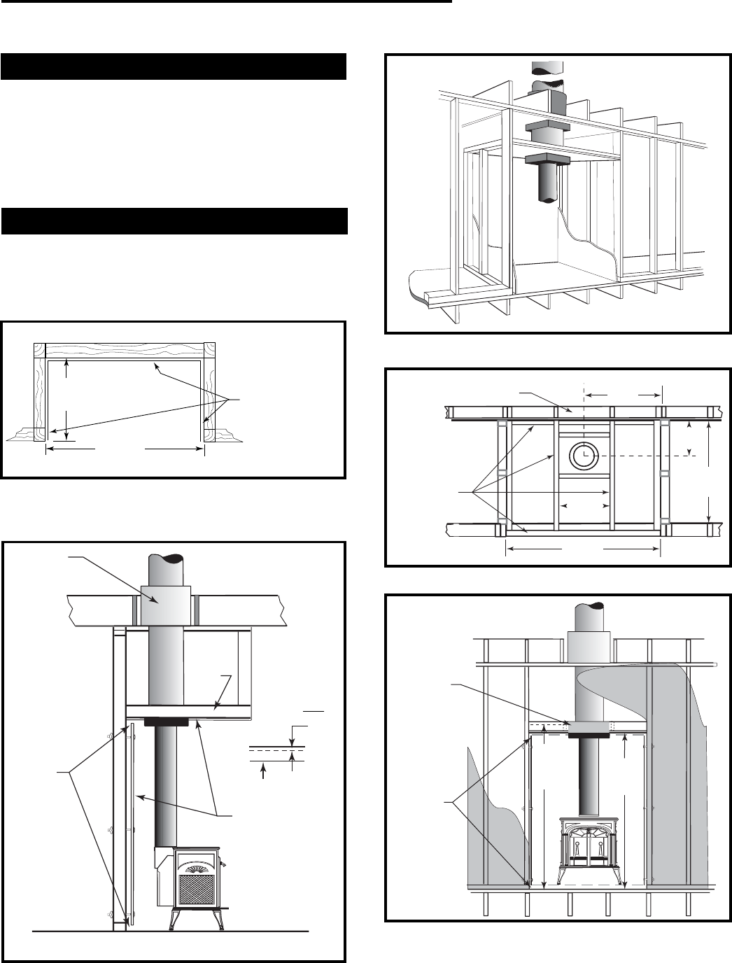
The following illustrations show noncombustible ceiling
framing and maximum and minimum permitted dimen-
sions for alcove construction.
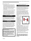
36"
Max.
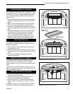
48" Min.
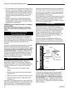
Fig. 22 Alcove floor plan. Sheetrock on front face butts to
Durock® (or equivalent) alcove lining.
Use recommended
floor protection
7/16" Durock®
(or equivalent)
spaced 1" off
wood studs on
non-combustible
spacers
ST502
INTREPID II
Metal
stud
A: This area, from
62" to 65" must be
covered with a
non-combustible
material
7/16" Durock®
(or equivalent)
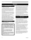
Fig. 23 Alcove side section.
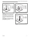
Joist shield
(supplied by
chimney
manufacturer)
1" air gaps,
top and
bottom, on
both sides
and back
wall
B: Combustible
facing may
overlap metal
studs by only 1"
B
A
ST503
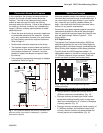
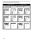
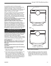
Fig. 24 Cutaway perspective of alcove installation.
ST504
24"
14¹⁄₄"
48" Min.
11"
Min.
36"
Min.
Metal studs
support 7/16"
Durock® (or
equivalent)
ceiling
Fig. 25 Reflected ceiling plan.
Existing combustible
framing
ST505
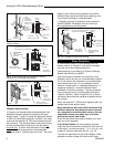
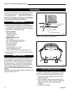
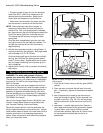
65"
62" Min.
to Alcove
Ceiling
Ceiling support
package
extends 2"
below Durock®
(or equivalent)
ceiling
1" air gap,
top and
bottom,
on both
sides and
back wall
Fig. 26 Front view: 65" minimum clearance from hearth to
combustibles on front face. Combustible facing may overlap
metal studs by only 1". It should not extend below the height
of the non-combustible ceiling.
ST506