


2. Properly seal joint using duct tape, mastic, or other approved
method. Do not allow mastic to come in contact with actuator.
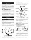
3. Insulate damper using 1-1/2-in. to 2-in. insulation. (Check
your local codes.) (See Fig. 7.)
NOTE: All zone dampers and ductwork must be properly sup-
ported according to local codes or SMACNA standards.
NOTE: There should be a minimum of 4 ft between the zone
damper and the first branch duct if more than 1 branch duct is
downstream of the zone damper.
ROUND FLEXIBLE DUCTWORK
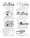
1. Slip 1 end of flexible ductwork over 1 end of zone damper.
(See Fig. 8.)
2. Secure the flexible duct to zone damper using SMACNA or
other approved method.
3. Properly seal joint using duct tape, mastic, or other approved
method. Do not allow mastic to come in contact with actuator.
4. Insulate damper using 1-1/2-in. to 2-in. insulation. (Check
your local codes.) (See Fig. 9.)
NOTE: All zone dampers and ductwork must be properly sup-
ported according to local codes or SMACNA standards.
RECTANGULAR FIBROUS GLASS DUCTWORK
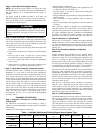
1. Insert 1 end of zone damper into 1 end of fibrous glass
ductwork approximately 2 to 3 in. (See Fig. 10.)
2. Screw field-supplied screws and tabs into zone damper.
3. Properly seal joint using duct tape, mastic, or other approved
method. Do not allow mastic to come in contact with actuators
4. Insulate damper using 1-1/2-in. to 2-in. insulation. (Check
your local codes.) (See Fig. 11.)
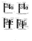
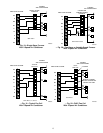
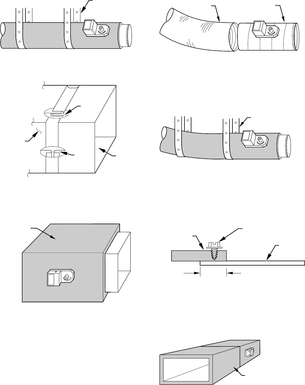
Fig. 5—Insulated Round Metal Ductwork
A95130
/ ″ STEEL STRAP
1
2
Fig. 6—Rectangular Metal Ductwork
A92478
DRIVE
ZONE
DAMPER
S-LOCK
SUPPLY
AIR DUCT
Fig. 7—Insulated Rectangular Metal Ductwork
A95131
1 / " TO 2"
INSULATION
1
2
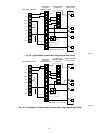
Fig 8—Round Flexible Ductwork
A95132
FLEXIBLE
DUCT
ZONE
DAMPER
Fig. 9—Insulated Round Flexible Ductwork
A95133
/ ″ STEEL STRAP
1
2
Fig. 10—Rectangular Fibrous Glass Ductwork
A92480
ZONE
DAMPER
2″ TO 3″
FIBROUS
GLASS
DUCTWORK
FIELD
SUPPLIED
SCREWS
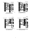
Fig. 11—Insulated Rectangular Fibrous Glass
Ductwork
A95134
1 / ″ TO 2″
INSULATION
1
2
3