


Step 2—Wiring
To prevent personal injury or possible equipment damage,
disconnect the power supply before routing wire.
All wiring must comply with local, state, and national codes.
NOTE: Use No. 18 AWG color-coded, insulated (35°C min)
wire. If thermostats are to be located more than 100 ft from the
WeatherMaker Two-Zone Center as measured along the control
voltage wires, use 16 AWG colored-coded wires to avoid exces-
sive voltage drop. All wiring is run back to the WeatherMaker
Two-Zone Center.
Step 3—Install WeatherMaker Two-Zone
NOTE: WeatherMaker Two-Zone is approved for indoor use
only and should never be installed with any of its components
exposed to the elements. Do not mount WeatherMaker Two-Zone
Center where it will be accessible to children. Do not locate the
center in areas of the home that are noise sensitive since relays are
energized and de-energized during operation and may be an
annoyance. Install WeatherMaker Two-Zone in an area with a
temperature range between 32°F and 150°F.
Install WeatherMaker Two-Zone center in a vertical position.
Locate in an area that is easily accessible in case servicing should
be required.
To prevent possible damage to the WeatherMaker Two-Zone
Center, do not mount on plenum, ductwork, or flush against
furnace.
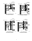
Step 4—Install Zone Dampers
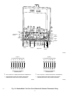
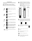
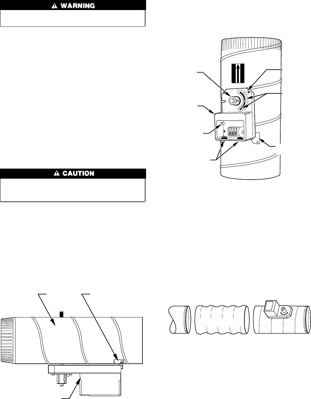
IMPORTANT: If conditions exist for possible condensing, the
motor must be positioned for adequate draining. (See Fig. 2.)
NOTE: If a multi-damper enabler is used to link dampers
together, then add 5va per damper to the transformer power supply
rating. Reference multi-damper enabler Installation Instructions.
Zone dampers may be installed in any direction.
Install dampers so the actuator is visible for inspection and
accessible in the event it would ever need service. The black mark
on the end of the damper shaft represents the position of the
damper blade.
NOTE: Insulate damper using 1-1/2 in. insulation (check local
codes). In areas where excessive condensing may occur, carefully
insulate over the actuator assembly. Make sure insulation does not
interfere with operation of actuator.
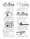
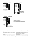
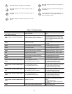
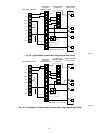
Before insulating the ductwork, check for proper damper opera-
tion. Apply 24vac between COM and OPN to open the damper and
COM and CLS to close the damper. (See Fig. 3.) The damper will
modulate counter-clockwise to open and clockwise to close.
If in an emergency it becomes necessary to force a damper open
manually, press in red quick blade release button with 1 hand and
turn mounting hub to reposition the damper shaft. Release button
to hold damper shaft in the new position.
To avoid noise and vibration, do not hard mount dampers to any
solid structure such as joists.
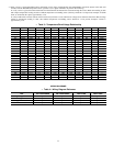
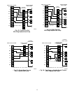
ROUND METAL DUCTWORK
IMPORTANT: If application exists with all metal ductwork
without insulation, flex connectors should be used on each end of
the zone dampers to avoid noise and vibration.
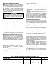
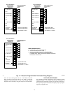
1. Crimp end of branch duct.
2. Slip end of flex connector over zone damper and use self-
tapping sheet metal screw to secure. (See Fig. 4.)
3. Properly seal joint using duct tape, mastic, or other approved
method. Do not allow mastic to come in contact with actuator.
4. Insulate damper using 1-1/2-in. to 2-in. insulation. (Check
your local codes.) (See Fig. 5.)
NOTE: All zone dampers and ductwork must be properly sup-
ported according to local codes or SMACNA standards.
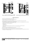
RECTANGULAR METAL DUCTWORK
1. Make connections using S-lock and drives. (See Fig. 6.)
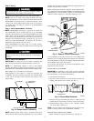
Fig. 2—Damper Motor Positioning
A95128
DAMPER MOUNTING
BRACKET
ACTUATOR
Fig. 3—Damper 24-vac Connections
A95096
90
45
0
CLS
COM
OPN
ACTUATOR
HOUSING
MOUNTING
BRACKET
QUICK BLADE
RELEASE
BUTTON
(RED)
FIELD
INSTALLED
POWER WIRING
ANGULAR
ROTATION
STOPS
POSITION
INDICATOR
MOUNTING
HUB
AIRFLOW
AIRFLOW
Fig. 4—Round Metal Ductwork
A95129
SUPPLY
FLEX
CONNECTOR
ZONE DAMPER
2
→