


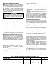
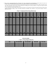
Table 3 shows a temperature/ohm/voltage relationship to help aid in troubleshooting the WeatherMaker Two-Zone System. This table will
evaluate both the Duct/HP temperature sensor operation. Use a digital multimeter to perform the following:
To verify a sensor is good, disconnect both leads from the I/O board and measure the resistance through the sensor. Match ohm reading to table
and compare temperature reading on table to ambient temperature surrounding sensor (Accuracy should be ± 5-10 percent). Example: if 10.92k
ohms are measured, this equals approximately 73°F.
To verify if I/O board is normal, reattach sensor to I/O board, set meter to 5vdc, and measure voltageacross terminal connections. Match voltage
reading to temperature reading in chart. The ambient temperature surrounding sensor should be ± 5-10 percent. Example: 2.61vdc is
approximately 73°F.
→ Table 3—Temperature/Ohm/Voltage Relationship
TEMP °F OHMS VOLTS TEMP °F OHMS VOLTS TEMP °F OHMS VOLTS TEMP °F OHMS VOLTS
30 34,367 3.873 73 10,921 2.610 117 4042 1.439 160 1693 0.724
32 32,654 3.828 75 10,449 2.555 118 3889 1.400 162 1637 0.703
34 31,030 3.781 77 10,000 2.500 120 3743 1.362 163 1582 0.683
36 29,498 3.734 79 9571 2.445 122 3603 1.324 165 1530 0.663
37 28,052 3.686 81 9164 2.391 124 3469 1.288 167 1480 0.645
39 26,686 3.637 82 8776 2.337 126 3340 1.252 169 1431 0.626
41 25,396 3.587 84 8407 2.284 127 3217 1.217 171 1385 0.608
43 24,171 3.537 86 8056 2.231 129 3099 1.183 172 1340 0.591
45 23,013 3.485 88 7720 2.178 131 2986 1.150 174 1297 0.574
46 21,918 3.433 90 7401 2.127 133 2878 1.117 176 1255 0.558
48 20,883 3.381 91 7096 2.075 135 2774 1.086 178 1215 0.542
50 19,903 3.328 93 6806 2.025 136 2675 1.055 180 1177 0.527
52 18,972 3.274 95 6530 1.975 138 2579 1.025 181 1140 0.512
54 18,090 3.220 97 6266 1.926 140 2488 0.996 183 1104 0.497
55 17,255 3.165 99 6014 1.878 142 2400 0.968 185 1010 0.483
57 16,464 3.111 100 5774 1.830 144 2315 0.940 187 1037 0.470
59 15,714 3.056 102 5546 1.784 145 2235 0.913 189 1005 0.457
61 15,000 3.000 104 5327 1.738 147 2157 0.887 190 974 0.444
63 14,323 2.944 106 5117 1.692 149 2083 0.862 — ——
64 13,681 2.889 108 4918 1.648 151 2011 0.837 — ——
66 13,071 2.833 109 4727 1.605 153 1943 0.813 — ——
68 12,493 2.777 111 4544 1.562 154 1876 0.790 — ——
70 11,942 2.721 113 4370 1.521 156 1813 0.767 — ——
72 11,418 2.666 115 4203 1.480 158 1752 0.745 — ——
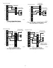
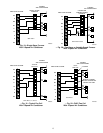
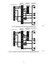
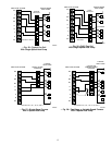
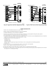
WIRING DIAGRAMS
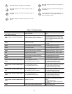
→ Table 4—Wiring Diagram Reference
OUTDOOR
UNIT
SINGLE-SPEED
AIR CONDITIONER
TWO-SPEED
AIR CONDITIONER
SINGLE-SPEED
HEAT PUMP
TWO-SPEED
HEAT PUMP
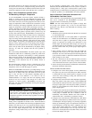
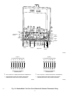
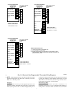
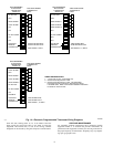
Single-Stage Furnace Fig. 15 Fig. 19 Fig. 23 Fig. 27
Two-Stage Furnace Fig. 16 Fig. 20 Fig. 24 Fig. 28
Typical Fan Coil Fig. 17 Fig. 21 Fig. 25 Fig. 29
FK4C Fan Coil Fig. 18 Fig. 22 Fig. 26 Fig. 30
11
→