


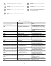
TROUBLESHOOTING
This section contains information to assist you in troubleshooting
problems and errors associated with the WeatherMaker Two-Zone
system. See Table 2.
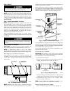
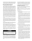
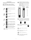
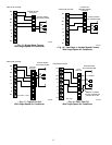
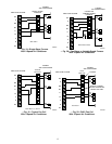
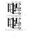
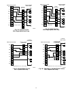
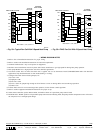
Step 1—System Diagram, Jumpers, and Switches
NOTE: For correct control board operation, it must have either a
sensor attached or a 10k resistor in place at the duct and HP inputs.
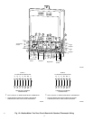
1
Fnc—Gas/electric thermostat is installed in
each zone.
Must be in this position to function prop-
erly.
HP—DO NOT USE.
Tstat
2
Fnc—Air conditioning equipment installed
is a cooling only unit.
HP—Air conditioning equipment installed
is a heat pump.
Equipmt
3
W/O FAN—When demand for heating ex-
ists, fan is controlled by gas/electric fur-
nace.
W/FAN—When demand for heating exists,
fan comes on immediately (heat pump
only).
Fnc Ht
4
DTO Off—When supply-air temperatures
approach a trip limit, HVAC equipment
will turn off. Dampers do not open until
equipment is locked out by control.
DTO On—When supply-air temperatures
approach a trip limit, closed dampers open
to maintain proper air temperatures.
DTO
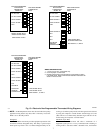
A
Damper Fuse—Protects damper from electrical dam-
age (3 Amp).
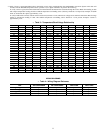
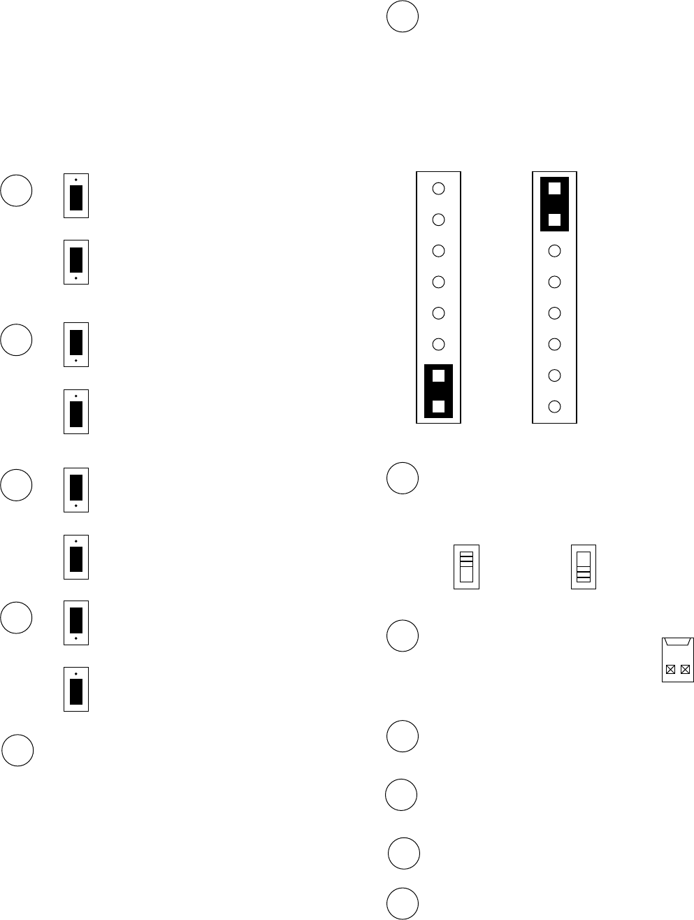
B
High Heating Temperature Trip Limit Setting —
When DTO is On, temperature is sensed by duct
temperature sensor. When the duct temperature
reaches this temperature setting, the duct temperature
optimizer is enabled.
If the LAT is exceeded then heating will turn off.
NOTE: HP temperature sensor is recommended for
all heat pump applications.
155°F
NORMAL HEAT
PUMP SETTING
NORMAL GAS/
ELECTRICAL
SETTING
147°F
138°F
130°F
122°F
113°F
105°F
155°F
147°F
138°F
130°F
122°F
113°F
105°F
175°F
164°F
153°F
143°F
132°F
121°F
110°F
EQUIPMENT
SHUTOFF
TEMPERATURE
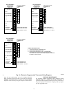
C
Emergency Heat Switch—This switch should remain
in the OFF position for both furnace and heat pump
operation. It should be switched to the ON position
only upon heat pump compressor failure to provide
emergency heat.
ON OFF
D
Comprotec Override—Momentarily short
pins together for temporary equipment time
delay override.
E
J6 jumper—Connects Rc and Rh inter-
nally.
F
Emergency heat LED—Will turn on when
emergency heat is on.
G
Red LED—Used for diagnostic errors.
H
Green LED—Flashes once every second
for normal operation, alternates with red
LED for diagnostic errors.
9
→