


8
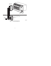
5. Drill two 3/16--in. mounting holes in wall where marked.
6. Secure mounting base to wall with 2 anchors and screws provided
(additional anchoring holes available for more secure mounting, if
needed) making sure all wires extend through hole in mounting base.
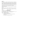
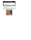
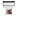
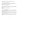
7. Adjust length and routing of each wire to reach proper terminal and
connector block on mounting base with 1/4 in. of extra wire. Strip only
1/4 in. of insulation from each wire to prevent adjacent wires from
shorting together when connected. See Fig. 2.
A08094
Fig. 2 -- Secure Wir es to Terminal Strip
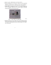
8. Mat ch and conne ct wir es fr om the PTA C unit to prope r ter m i nal s on the the r-
mos t at connec t or blocks (s ee Fig. 3). Do not re m ove fact or y--inst alle d jumpe r
wire fr om Rc and Rh termi nals. The R wire from t he PTAC ca n be conne c-
ted to either position.