


11
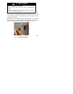
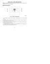
11. Close thermostat assembly making sure pins on back of circuit board
align with sockets in connector.
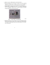
12. Turn ON power to unit.
Whe n power is appli ed, all di spl ay ic ons ar e li t f or 2 s ec onds to test the display.
Followi ng this , the equipm ent type for which the thermos ta t i s configure d is
displaye d for an addi tional 2 seconds . It will be one of PH or PC (if HP, AC, H or C
is di spl aye d, t he t her most at is confi gure d inc orr ec t ly t o oper at e a PTAC). S ee
expla nat i on under St ep 3, Option 01 be low. A he at pump the rmos ta t, conf igur ed to
opera t e a Hea tCool unit ( se e Option 1 below), wi l l dis pl ay PC. A He at Cool
ther most at ca nnot be configur ed to opera t e a Hea tPump unit.
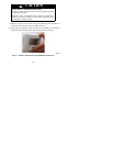
NOTE: If a common wire has not been connected, two AA batteries must be
used to power the thermostat.
Step 3 — Set Thermostat Configuration
Configurat ion opti ons ena bl e the i nst alle r to conf i gure the the rmos ta t for a par ticul ar
installation. These must be set correctly to insure proper PT AC operation. Following
is a lis t of the options ava il able, an expl ana t ion of the ir function, and the ir fa ct ory
defa ult se t ti ngs.
Configuration Options -- Summary:
Option 01 -- Equipment type
Option 03 -- Fahrenheit/Centigrade
Option 04 -- Unused for PTAC
Option 07 -- Unused for PTAC
Option 10 -- Reversing valve (HP only)
Option 11 -- Minimum deadband between heating and cooling setpoints
Option 13 -- Room air temperature offset adjustment
Option 16 -- Maximum cycles per hour