


Carrier
Carrier Indoor & Outdoor Split Geothermal Heat Pumps - Rev.: 08/10/05
40
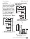
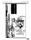
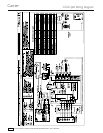
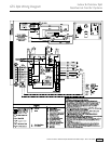
CXM Control
For detailed control information, see CXM/DXM
Application, Operation and Maintenance (AOM) manual
(part #97B0003N08).
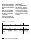
Field Selectable Inputs
Test mode: Test mode allows the service technician to
check the operation of the control in a timely manner. By
momentarily shorting the test terminals, the CXM control
enters a 20 minute test mode period in which all time
delays are sped up 15 times. Upon entering test mode,
the status LED will fl ash a code representing the last
fault. For diagnostic ease at the thermostat, the alarm
relay will also cycle during test mode. The alarm relay
will cycle on and off similar to the status LED to indicate
a code representing the last fault, at the thermostat. Test
mode can be exited by shorting the test terminals for 3
seconds.
Retry Mode: If the control is attempting a retry of a fault,
the status LED will slow fl ash (slow fl ash = one fl ash
every 2 seconds) to indicate the control is in the process
of retrying.
Field Confi guration Options
Note: In the following fi eld confi guration options, jumper
wires should be clipped ONLY when power is removed
from the CXM control.
Water coil low temperature limit setting: Jumper 3 (JW3-
FP1 Low Temp) provides fi eld selection of temperature
limit setting for FP1 of 30°F or 10°F [-1°F or -12°C]
(refrigerant temperature).
Not Clipped = 30°F [-1°C]. Clipped = 10°F [-12°C].
Air coil low temperature limit setting: Jumper 2 (JW2-
FP2 Low Temp) provides fi eld selection of temperature
limit setting for FP2 of 30°F or 10°F [-1°F or -12°C]
(refrigerant temperature). Note: This jumper should
only be clipped under extenuating circumstances, as
recommended by the factory.
Not Clipped = 30°F [-1°C]. Clipped = 10°F [-12°C].
Alarm relay setting: Jumper 1 (JW1-AL2 Dry) provides
fi eld selection of the alarm relay terminal AL2 to
be jumpered to 24VAC or to be a dry contact (no
connection).
Not Clipped = AL2 connected to R. Clipped = AL2 dry
contact (no connection).
DIP Switches
Note: In the following fi eld confi guration options, DIP
switches should only be changed when power is
removed from the CXM control.
DIP switch 1: Unit Performance Sentinel Disable -
provides fi eld selection to disable the UPS feature.
On = Enabled. Off = Disabled.
DIP switch 2: Stage 2 Selection - provides selection of
whether compressor has an “on” delay. If set to stage
2, the compressor will have a 3 second delay before
energizing. Also, if set for stage 2, the alarm relay will
NOT cycle during test mode.
On = Stage 1. Off = Stage 2
DIP switch 3: Not Used.
DIP switch 4: DDC Output at EH2 - provides selection
for DDC operation. If set to “DDC Output at EH2,” the
EH2 terminal will continuously output the last fault code
of the controller. If set to “EH2 normal,” EH2 will operate
as standard electric heat output.
On = EH2 Normal. Off = DDC Output at EH2.
NOTE: Some CXM controls only have a 2 position DIP
switch package. If this is the case, this option can be
selected by clipping the jumper which is in position 4
of SW1.
Jumper not clipped = EH2 Normal. Jumper clipped =
DDC Output at EH2.
DIP switch 5: Factory Setting - Normal position is “On.”
Do not change selection unless instructed to do so by
the factory.
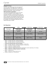
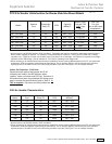
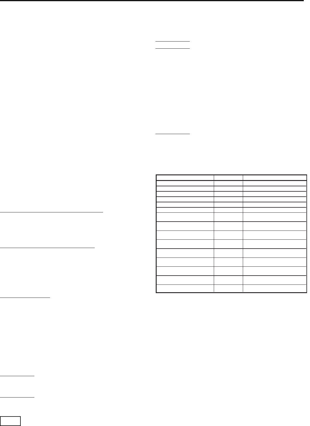
-Slow Flash = 1 fl ash every 2 seconds
-Fast Flash = 2 fl ashes every 1 second
-Flash code 2 = 2 quick fl ashes, 10 second pause, 2 quick
fl ashes, 10 second pause, etc.
-On pulse 1/3 second; off pulse 1/3 second
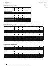
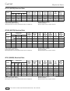
Description of Operation LED Alarm Relay
Normal Mode On Open
Normal Mode with UPS Warning On Cycle (closed 5 sec., Open 25 sec.)
CXM is non-functional Off Open
Fault Retry Slow Flash Open
Lockout Fast Flash Closed
Over/Under Voltage Shutdown Slow Flash Open (Closed after 15 minutes)
Test Mode - No fault in memory Flashing Code 1 Cycling Code 1
Test Mode - HP Fault in memory Flashing Code 2 Cycling Code 2
Test Mode - LP Fault in memory Flashing Code 3 Cycling Code 3
Test Mode - FP1 Fault in memory Flashing Code 4 Cycling Code 4
Test Mode - FP2 Fault in memory Flashing Code 5 Cycling Code 5
Test Mode - CO Fault in memory Flashing Code 6 Cycling Code 6
Test Mode - Over/Under
shutdown in memory
Flashing Code 7 Cycling Code 7
Test Mode - UPS in memory Flashing Code 8 Cycling Code 8
Test Mode - Swapped Thermistor Flashing Code 9 Cycling Code 9
CXM LED And Alarm Relay Operations
CXM Controls