


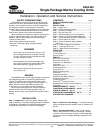
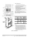
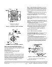
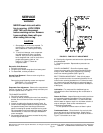
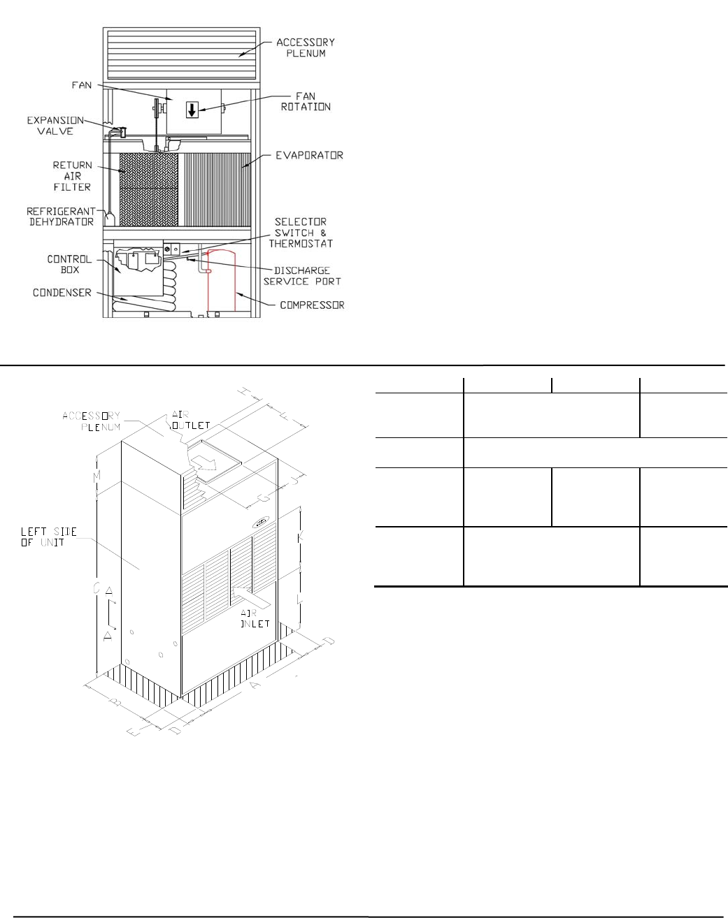
FIGURE 1 - BASE UNIT INTERIOR DETAILS
(TYPICAL UNIT SHOWN)
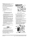
Step 4 - Rig and Place Unit -
NOTE: Install accessories before placing unit.
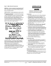
a. Provide space around unit for service, filter access, and
overhead clearance as indicated in Figure 2.
b. Move and store unit in upright position.
c. Use slings with spacer under base skid to prevent panel
damage when using hoist.
d. Units as shipped are adequately dampened against
vibration. If additional dampening is desired, place
sponge rubber or rubber mat, between deck and base of
unit or install vibration isolators.
e. Unit should be level. Unit leveling tolerance is 1/8 in. per
linear ft in any direction.
Step 5 - Install Accessory Plenum (If Supplied) - Use
plenum as template to mark hole locations in top panel. Drill
0.154-in. holes in top panel at marked locations and attach
plenum with screws supplied.
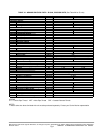
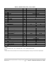
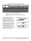
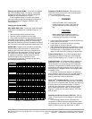
UNIT *04 *06 *08,*12
A
B
C
36.13(918)
21.63(549)
59.25(1505)
48.26(1226)
29.88(759)
72.00(1828)
D SEE NOTE 2
E 24(51)
F
G
H
J
11.25(286)
13.00 (330)
0.75(19)
11.59(294)
13.50(343)
15.50(394)
0.75(19)
10.34(263)
15.63(397)
18.38(466)
1.00 (25)
11.37(289)
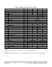
K
L
M
17.13(435)
20.38(519)
17.11(435)
24.20(615)
25.50(646)
17.11(435)
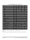
NOTES:
1. Certified dimension drawings available upon request
2. Minimum required clearance at back of unit is zero.
Clearance above and at right (90MA*08,*12 only) and at
left of unit depends on space required for accessory
plenum, ductwork, condenser piping, accessory heater
piping, condensate drain line and power wiring
3. Water connections are located on left side of unit (Refer
to “Make Condenser Connections”, Condensate drain
connections are located on left side of unit for *04 & *06,
and on both sides of unit for *08 & *12.
FIGURE 2 - UNIT DIMENSIONS
Manufacturer reserves the right to discontinue, or change at any time, specifications or designs without notice and without incurring obligations
Printed in U.S.A. 90MA-3SI SUPERCEDES FORM 62-02971-00 09-2009
Pg 8