


Charging the System (90MA) - These units are shipped
with a full operating charge. If recharging is necessary
(complete charge lost), weigh in amount of refrigerant
indicated on unit nameplate and in Table 1.
If unit has partial charge, it must be recharged by
removing existing charge and recharging by weighing in
the required amount of refrigerant. (Refer to Table
1A/B/C/2A/B/C)
Charging the System (90MU)
UNIT SIZES 90MU Units - These units, used with remote
condensers, are shipped with a holding charge only. To
charge:
1. Open discharge and liquid service valves.
2. Leak test, reclaim refrigerant and evacuate.
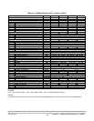
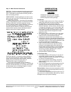
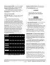
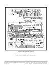
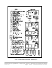
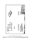
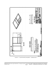
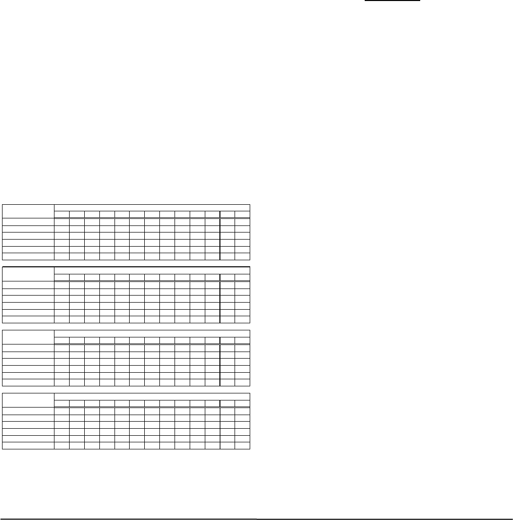
3. Using standard refrigerant charging techniques and
subcooling charts (Figure 11) add refrigerant as required
to maintain proper operating conditions. Subcooling is
determined by subtracting the actual temperature entering
the TXV from the saturated temperature entering the TXV.
IMPORTANT: Charge on both the HIGH and LOW side
simultaneously of idle compressors to prevent axial
loading of the scroll, which may cause a temporary no
start condition for the compressor. If this occurs, leave
the system off for approximately 30 minutes. Attempt
to restart the compressor; internal pressures should
equalize enough to allow compressor to start.
If removing the compressor, evacuate both the HIGH
and LOW side simultaneously.
137 149 162 176 205 222 239 256 275 295 315 336 359
0
70 75 80 85 90 95 100 105 110 115 120 125 130
5
65 70 75 80 85 90 95 100 105 110 115 120 125
10
60 65 70 75 80 85 90 95 100 105 110 115 120
15
55 60 65 70 75 80 85 90 95 100 105 110 115
20
50 55 60 65 70 75 80 85 90 95 100 105 110
25
45 50 55 60 65 70 75 80 85 90 95 100 105
150 163 176 190 205 221 237 255 273 292 313 334 356
0
70 75 80 85 90 95 100 105 110 115 120 125 130
5
65 70 75 80 85 90 95 100 105 110 115 120 125
10
60 65 70 75 80 85 90 95 100 105 110 115 120
15
55 60 65 70 75 80 85 90 95 100 105 110 115
20
50 55 60 65 70 75 80 85 90 95 100 105 110
25
45 50 55 60 65 70 75 80 85 90 95 100 105
1100 1200 1300 1400 1500 1600 1700 1800 1900 2000 2100 2200 2300
0
23 26 29 32 34 37 39 42 44 46 48 50 52
3
20 23 26 29 31 34 36 39 41 43 45 47 49
5
18 21 24 27 29 32 34 37 39 41 43 45 47
7
16 19 22 25 27 30 32 35 37 39 41 43 45
10
13 16 19 22 24 27 29 32 34 36 38 40 42
13
10 13 16 19 21 24 26 29 31 33 35 37 39
1190 1288 1392 1503 1580 1701 1786 1918 2011 2107 2206 2308 2414
0
23 26 29 32 34 37 39 42 44 46 48 50 52
3
20 23 26 29 31 34 36 39 41 43 45 47 49
5
18 21 24 27 29 32 34 37 39 41 43 45 47
7
16 19 22 25 27 30 32 35 37 39 41 43 45
10
13 16 19 22 24 27 29 32 34 36 38 40 42
13
10 13 16 19 21 24 26 29 31 33 35 37 39
Required
Subcooling (ºC)
R404A PRESSURE AT LIQUID LINE SERVICE VALVE kPa
Required
Subcoolin
g
(
ºF
)
R407C PRESSURE AT LIQUID LINE SERVICE VALVE PSIG
Required
Subcooling (ºF)
R404A PRESSURE AT LIQUID LINE SERVICE VALVE PSIG
Required
Subcooling (ºC)
R407C PRESSURE AT LIQUID LINE SERVICE VALVE kPa
FIGURE 11 - CHARGING CHARTS
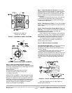
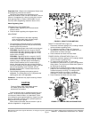
Evaporator-Fan Motor Removal - Motor power wires
need not be disconnected from motor terminals before
motor is removed from unit.
1. Shut off unit main power supply.
WARNING
LOCK OPEN AND TAG unit disconnect
before working on fan motor. Remove fuses
and take them with you after noting this on
tag.
CAUTION
Before attempting to remove fan motors or
motor mounts, place a piece of plywood over
evaporator coils to prevent coil damage.
2. Loosen motor hold down bolts on mounting bracket so
that fan belt can be removed.
3 Loosen but do not remove the 2 motor mounting
bracket bolts on left side of bracket.
4 Slide motor/bracket assembly to extreme right, remove
bolts and lift out through space between fan scroll and
side Rest motor on a high platform such as a step
ladder. Do not allow motor to hang by its power wires.
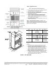
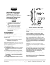
Pressure Relief Device - All units are equipped with a
fusible-plug type safety relief device an the refrigerant
tubing. The relief setting is 197 °F to 203 °F on all units.
Crankcase Heater - A Crankcase heater is supplied on
90MA,MU*08 and *12 size units. The heater prevents
liquid refrigerant from accumulating in the compressor
crankcase during extended shutdown periods. Heater is
automatically energized whenever unit main power is on
and compressor is stopped. Heater is de-energized when
compressor starts.
Do not shut off main power supply for an extended
period except for servicing unit. Turn on power supply for
at least 24 hours after an extended shutdown before
starting compressor. Refer to “Operation”.
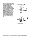
Cycle-Loc
TM
- Protection Device - All units are equipped
with Cycle-LOC current-sensing lockout relay. This device
will lock out the compressor after any safety trip (discharge
pressure switch, suction-pressure switch, or internal
overload of the compressor). Check reason for lockout
before resetting the device. Refer to unit label wiring
diagram. To reset, turn the system switch to OFF, then
back to COOL.
Discharge and Suction Pressure Switches - Refer to
Table 1 for opening and closing settings for these safety
devices.
The discharge pressure switch is located on the
compressor on 06DA compressor equipped units and on
the discharge line on all other units. The suction pressure
switch is located on top of the compressor on 06DA
Manufacturer reserves the right to discontinue, or change at any time, specifications or designs without notice and without incurring obligations
Printed in U.S.A. 90MA-3SI SUPERCEDES FORM 62-02971-00 09-2009
Pg 15