


Manufacturer reserves the right to discontinue, or change at any time, specifications or designs without notice and without incurring obligations
Printed in U.S.A. 90MA-3SI SUPERCEDES FORM 62-02971-00 09-2009
Pg 10
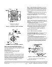
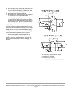
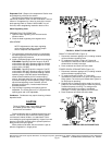
a. Route regulating valve capillary with its flare nut to the
fitting on refrigerant discharge line (Figure. 1), using
any convenient unused opening on side of unit. Use a
grommet in panel to prevent chafing of capillary.
b. Remove cap from discharge line fitting.
c. Remove cotter pin taped to discharge line fitting. Insert
pin, split end first, into regulating valve flare
d. Hold flare tightly against fitting while connecting flare
nut. Round end of cotter pin will depress core of fitting.
The opened fitting allows refrigerant pressure to act on
water regulating valve. Tighten nut to prevent leakage.
Fitting automatically seals when nut is removed.
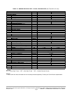
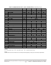
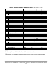
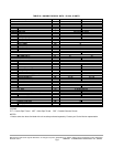
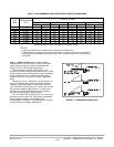
90MU UNITS-Install remote mounted condenser in
accordance with the installation instructions provided with
condenser. Recommended line sizes are given in Table 3.
Additional instructions can be found in Carrier System
Design Manual, Part 3, for standard refrigeration piping
techniques. On *08 and *12 size units, secure discharge
line to bracket at unit outlet using proper clamp from
supplied fastener package
Condenserless (90MU) units are shipped with a
refrigerant holding charge. After refrigerant connections
are made, leak test, reclaim refrigerant, evacuate, and
charge system as described in “Service, Charging The
System”.
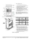
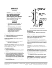
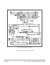
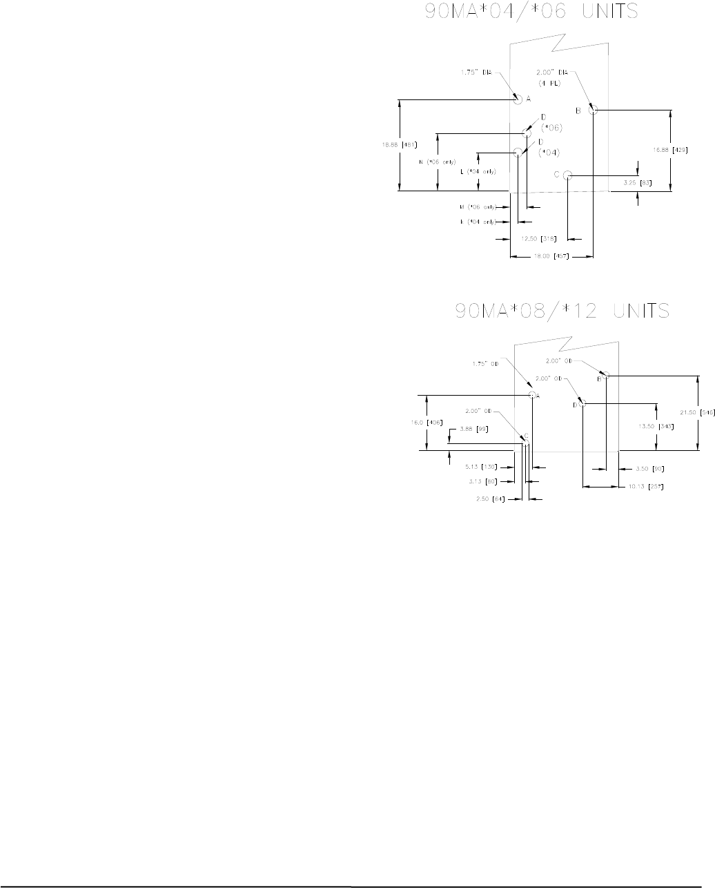
A = Condensate, ¾ inch Female Pipe Thread,
B = Electrical Opening,
C = Condenser In, 1 inch FPT,
D = Condenser Out, 1 Inch FPT
FIGURE 6 - CONNECTION LOCATIONS