


40
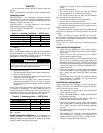
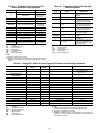
Table 17 — Antifreeze Percentages by Volume
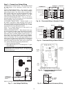
Cooling Tower/Boiler Systems — These systems
typically use a common loop maintained at 60 to 90 F. The use
of a closed circuit evaporative cooling tower with a secondary
heat exchanger between the tower and the water loop is recom-
mended. If an open type cooling tower is used continuously,
chemical treatment and filtering will be necessary.
Ground Coupled, Closed Loop and Plateframe
Heat Exchanger Well Systems — These systems al-
low water temperatures from 30 to 110 F. The external loop
field is divided up into 2 in. polyethylene supply and return
lines. Each line has valves connected in such a way that upon
system start-up, each line can be isolated for flushing using
only the system pumps. Air separation should be located in the
piping system prior to the fluid re-entering the loop field.
OPERATION
Power Up Mode —
The unit will not operate until all the
inputs, terminals and safety controls are checked for normal
operation.
NOTE: The compressor will have a 5-minute anti-short cycle
upon power up.
Units with Aquazone™ Complete C Control
STANDBY — Y and W terminals are not active in standby
mode, however the O and G terminals may be active, depend-
ing on the application. The compressor will be off.
COOLING — Y and O terminals are active in Cooling mode.
After power up, the first call to the compressor will initiate a
5 to 80 second random start delay and a 5-minute anti-short
cycle protection time delay. After both delays are complete, the
compressor is energized.
NOTE: On all subsequent compressor calls the random start
delay is omitted.
HEATING STAGE 1 — Terminal Y is active in heating
stage 1. After power up, the first call to the compressor will
initiate a 5 to 80 second random start delay and a 5-minute anti-
short cycle protection time delay. After both delays are
complete, the compressor is energized.
NOTE: On all subsequent compressor calls the random start
delay is omitted.
HEATING STAGE 2 — To enter Stage 2 mode, terminal W is
active (Y is already active). Also, the G terminal must be active
or the W terminal is disregarded. The compressor relay will re-
main on and EH1 is immediately turned on. EH2 will turn on
after 10 minutes of continual stage 2 demand.
NOTE: EH2 will not turn on (or if on, will turn off) if FP1 tem-
perature is greater than 45 F and FP2 is greater than 110 F.
EMERGENCY HEAT — In emergency heat mode, terminal
W is active while terminal Y is not. Terminal G must be active
or the W terminal is disregarded. EH1 is immediately turned
on. EH2 will turn on after 5 minutes of continual emergency
heat demand.
Units with Aquazone Deluxe D Control
STANDBY/FAN ONLY — The compressor will be off. The
Fan Enable, Fan Speed, and reversing valve (RV) relays will be
on if inputs are present. If there is a Fan 1 demand, the Fan
Enable will immediately turn on. If there is a Fan 2 demand,
the Fan Enable and Fan Speed will immediately turn on.
NOTE: DIP switch 5 on S1 does not have an effect upon Fan 1
and Fan 2 outputs.
HEATING STAGE 1 — In Heating Stage 1 mode, the Fan
Enable and Compressor relays are turned on immediately.
Once the demand is removed, the relays are turned off and the
control reverts to Standby mode. If there is a master/slave or
dual compressor application, all compressor relays and related
functions will operate per their associated DIP switch 2 setting
on S1.
HEATING STAGE 2 — In Heating Stage 2 mode, the Fan
Enable and Compressor relays remain on. The Fan Speed relay
is turned on immediately and turned off immediately once the
demand is removed. The control reverts to Heating Stage 1
mode. If there is a master/slave or dual compressor application,
all compressor relays and related functions will operate per
their associated DIP switch 2 setting on S1.
HEATING STAGE 3 — In Heating Stage 3 mode, the Fan
Enable, Fan Speed and Compressor relays remain on. The EH1
output is turned on immediately. With continuing Heat Stage 3
demand, EH2 will turn on after 10 minutes. EH1 and EH2 are
turned off immediately when the Heating Stage 3 demand is re-
moved. The control reverts to Heating Stage 2 mode.
Output EH2 will be off if FP1 is greater than 45 F AND
FP2 (when shorted) is greater than 110 F during Heating
Stage 3 mode. This condition will have a 30-second recogni-
tion time. Also, during Heating Stage 3 mode, EH1, EH2, Fan
Enable, and Fan Speed will be ON if G input is not active.
EMERGENCY HEAT — In Emergency Heat mode, the Fan
Enable and Fan Speed relays are turned on. The EH1 output is
turned on immediately. With continuing Emergency Heat de-
mand, EH2 will turn on after 5 minutes. Fan Enable and Fan
Speed relays are turned off after a 60-second delay. The control
reverts to Standby mode.
Output EH1, EH2, Fan Enable, and Fan Speed will be ON if
the G input is not active during Emergency Heat mode.
COOLING STAGE 1 — In Cooling Stage 1 mode, the Fan
Enable, compressor and RV relays are turned on immediately.
If configured as stage 2 (DIP switch set to OFF) then the com-
pressor and fan will not turn on until there is a stage 2 demand.
The fan Enable and compressor relays are turned off immedi-
ately when the Cooling Stage 1 demand is removed. The con-
trol reverts to Standby mode. The RV relay remains on until
there is a heating demand. If there is a master/slave or dual
compressor application, all compressor relays and related func-
tions will track with their associated DIP switch 2 on S1.
COOLING STAGE 2 — In Cooling Stage 2 mode, the Fan
Enable, compressor and RV relays remain on. The Fan Speed
relay is turned on immediately and turned off immediately
once the Cooling Stage 2 demand is removed. The control re-
verts to Cooling Stage 1 mode. If there is a master/slave or dual
compressor application, all compressor relays and related func-
tions will track with their associated DIP switch 2 on S1.
NIGHT LOW LIMIT (NLL) STAGED HEATING — In NLL
staged Heating mode, the override (OVR) input becomes ac-
tive and is recognized as a call for heating and the control will
immediately go into a Heating Stage 1 mode. With an addition-
al 30 minutes of NLL demand, the control will go into Heating
Stage 2 mode. With another additional 30 minutes of NLL
demand, the control will go into Heating Stage 3 mode.
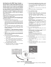
Units with WSHP Open Multiple Protocol —
The WSHP Open multi-protocol controller will control me-
chanical cooling, heating and waterside economizer outputs
based on its own space temperature input and set points. An
optional CO
2
IAQ (indoor air quality) sensor mounted in the
space can maximize the occupant comfort. The WSHP Open
controller has its own hardware clock that is automatically set
ANTIFREEZE
MINIMUM TEMPERATURE FOR
FREEZE PROTECTION (F)
0° 10 20 30
Methanol (%) 25 21 16 10
Propylene Glycol (%) 26 23 19 9
Ethylene Glycol (%) 24 20 16 12