


35
PRE-START-UP
System Checkout —
When the installation is complete
and the system is cleaned and flushed, follow the System
Checkout procedure outlined below.
1. Voltage: Ensure that the voltage is within the utilization
range specifications of the unit compressor and fan motor.
2. System Water Temperature: Ensure that the system
water temperature is within an acceptable range to facili-
tate start-up. (When conducting this check, also verify
proper heating and cooling set points.)
3. System Water pH: Verify system water acidity
(pH = 7.5 or 8.5). Proper pH promotes the longevity of
hoses and heat exchangers.
4. System Flushing: Properly clean and flush the system
periodically. Ensure that all supply and return hoses are
connected end-to-end to facilitate system flushing and
prevent fouling of the heat exchanger by system water.
Water used in the system must be potable and should not
contain dirt, piping slag, and chemical cleaning agents.
5. Closed-Type Cooling Tower or Open Tower with Heat
Exchanger: Check equipment for proper temperature set
points and operation.
6. Verify Balanced Water Flow Rate to Heat Pump.
7. Standby Pump: Verify that the standby pump is properly
installed and in operating condition.
8. Access Panels: Assure that all access panels in the filter
and fan section are securely closed.
9. Air Dampers: Assure that all air dampers are properly
set.
10. System Controls: To ensure that no catastrophic system
failures occur, verify that system controls are functioning
and that the sequencing is correct.
11. Freeze Protection for Water System: Verify that freeze
protection is provided for the building loop water system
when outdoor design conditions require it. Inadequate
freeze protection can lead to expensive tower and system
piping repairs.
12. System Water Loop: Verify that all air is bled from the
system. Air in the system impedes unit operation and
causes corrosion in the system piping.
13. Unit Filters: To avoid system damage, check that the unit
filter is clean.
14. Unit Fans: Manually rotate fans to assure free rotation.
Ensure that fans are properly secured to the fan shaft. Do
not oil fan motors on start-up since they are lubricated at
the factory.
15. System Control Center: Examine the system control
and alarm panel for proper installation and operation to
ensure control of the temperature set-points for operation
of the system’s heat rejector and boiler (when used).
16. Miscellaneous: Note any questionable aspects of the
installation.
17. Air Coil: To obtain maximum performance, the air coil
should be cleaned before starting the unit. A ten percent
solution of dishwasher detergent and water is recom-
mended for both sides of the coil. Rinse thoroughly with
water.
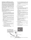
FIELD SELECTABLE INPUTS
Jumpers and DIP (dual in-line package) switches on the
control board are used to customize unit operation and can be
configured in the field.
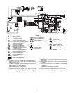
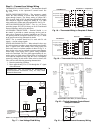
Complete C Control Jumper Settings (See
Fig. 6 and 7)
WATER COIL FREEZE PROTECTION (FP1) LIMIT
SETTING — Select jumper 3, (JW3-FP1 Low Temp) to
choose FP1 limit of 10 F or 30 F. To select 30 F as the limit,
DO NOT clip the jumper. To select 10 F as the limit, clip the
jumper.
AIR COIL FREEZE PROTECTION (FP2) LIMIT SET-
TING — Select jumper 2 (JW2-FP2 Low Temp) to choose
FP2 limit of 10 F or 30 F. To select 30 F as the limit, DO NOT
clip the jumper. To select 10 F as the limit, clip the jumper.
ALARM RELAY SETTING — Select jumper 1 (JW1-AL2
Dry) for connecting alarm relay terminal (AL2) to 24 vac (R)
or to remain as a dry contact (no connection). To connect AL2
to R, do not clip the jumper. To set as dry contact, clip the
jumper.
Complete C Control DIP Switches — The Com-
plete C control has 1 DIP switch block with two switches. See
Fig. 6 and 7.
PERFORMANCE MONITOR (PM) — DIP switch 1 will
enable or disable this feature. To enable the PM, set the switch
to ON. To disable the PM, set the switch to OFF.
STAGE 2 — DIP switch 2 will enable or disable compressor
delay. Set DIP switch to OFF for stage 2 in which the compres-
sor will have a 3-second delay before energizing.
NOTE: The alarm relay will not cycle during Test mode if
switch is set to OFF, stage 2.
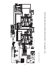
Deluxe D Control Jumper Settings (See Fig. 9
and 10)
WATER COIL FREEZE PROTECTION (FP1) LIMIT
SETTING — Select jumper 3, (JW3-FP1 Low Temp) to
choose FP1 limit of 10 F or 30 F. To select 30 F as the limit, DO
NOT clip the jumper. To select 10 F as the limit, clip the jumper.
AIR COIL FREEZE PROTECTION (FP2) LIMIT SET-
TING — Select jumper 2 (JW2-FP2 Low Temp) to choose
FP2 limit of 10 F or 30 F. To select 30 F as the limit, DO NOT
clip the jumper. To select 10 F as the limit (for anti-freeze sys-
tems), clip the jumper.
ALARM RELAY SETTING — Select jumper 4 (JW4-AL2
Dry) for connecting alarm relay terminal (AL2) to 24 vac (R)
or to remain as a dry contact (no connection). To connect AL2
to R, do not clip the jumper. To set as dry contact, clip the
jumper.
LOW PRESSURE SETTING — The Deluxe D control can
be configured for Low Pressure Setting (LP). Select jumper 1
(JW1-LP Norm Open) for choosing between low pressure in-
put normally opened or closed. To configure for normally
closed operation, do not clip the jumper. To configure for nor-
mally open operation, clip the jumper.
Deluxe D Control DIP Switches — The Deluxe D
control has 2 DIP switch blocks. Each DIP switch block has 8
switches and is labeled either S1 or S2 on the circuit board.
DIP SWITCH BLOCK 1 (S1) — This set of switches offers
the following options for Deluxe D control configuration:
Performance Monitor (PM)
— Set switch 1 to enable or dis-
able performance monitor. To enable the PM, set the switch to
ON. To disable the PM, set the switch to OFF.
Compressor Relay Staging Operation
— Switch 2 will en-
able or disable compressor relay staging operation. The com-
pressor relay can be set to turn on with stage 1 or stage 2 call
IMPORTANT: Jumpers and DIP switches should only
be clipped when power to control board has been turned
off.