


39
e. Enter ON/OFF time, then press continue.
f. Press OK to apply and save to a particular day of
the week.
g. Continue to add the same or different schedule spe-
cific days of the week.
To add exceptions to the schedule:
i. Press Add softkey.
ii. Select exception type from following:
• Date
• Date Range
• Week-N-Day
• Calender Reference
9. Go back to Home Screen.
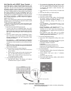
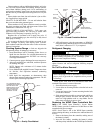
10. Remove BACview
6
cable from SPT sensor by reversing
the process in Step 1.
11. Perform system test.
Flow Regulation — Flow regulation can be accom-
plished by two methods. Most water control valves have a flow
adjustment built into the valve. By measuring the pressure drop
through the unit heat exchanger, the flow rate can be deter-
mined. Adjust the water control valve until the flow of 1.5 to 2
gpm is achieved. Since the pressure constantly varies, two
pressure gages may be needed in some applications.
An alternative method is to install a flow control device.
These devices are typically an orifice of plastic material de-
signed to allow a specified flow rate that are mounted on the
outlet of the water control valve. Occasionally these valves
produce a velocity noise that can be reduced by applying some
back pressure. To accomplish this, slightly close the leaving
isolation valve of the well water setup.
System Cleaning and Flushing — Cleaning and
flushing the unit is the single most important step to ensure
proper start-up and continued efficient operation of the system.
Follow the instructions below to properly clean and flush the
system:
1. Verify that electrical power to the units is disconnected.
2. Install the system with the supply hose connected directly
to the return riser valve. Use a single length of flexible
hose.
3. Open all air vents. Fill the system with water. Do not al-
low system to overflow. Bleed all air from the system.
Check the system for leaks and repair appropriately.
4. Verify that all strainers are in place. Start the pumps and
systematically check each vent to ensure that all air is
bled from the system.
5. Verify that makeup water is available. Adjust makeup
water appropriately to replace the air which was bled
from the system. Check and adjust the water/air level in
the expansion tank.
6. Set the boiler (when used) to raise the loop temperature to
approximately 85 F. Open a drain at the lowest point in
the system. Adjust the makeup water replacement rate to
equal the rate of bleed.
7. Refill the system and add trisodium phosphate in a pro-
portion of approximately one pound per 150 gallons of
water. Reset the boiler (when used) to raise the loop tem-
perature to about 100 F. Circulate the solution for a
minimum of eight to 24 hours. At the end of this period,
shut off the circulating pump and drain the solution. Re-
peat system cleaning if necessary.
8. When the cleaning process is complete, remove the short-
circuited hoses. Reconnect the hoses to the proper supply
and return the connections to each of the rooftop units.
Refill the system and bleed off all air.
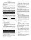
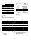
9. Add antifreeze to the system in climates where ambient
temperature falls below freezing, using the proportion of
antifreeze shown in Table 17. The volume of antifreeze
required will vary based on outdoor design temperature.
10. Test the system pH with litmus paper. The system water
should be slightly alkaline ( pH 7.5 to 8.5). Add chemi-
cals as appropriate to maintain acidity levels.
11. When the system is successfully cleaned, flushed, refilled
and bled, check the main system panels, safety cutouts,
and alarms. Set the controls to properly maintain loop
temperatures.
NOTE: Carrier strongly recommends all piping connections,
both internal and external to the unit, be pressure tested by an
appropriate method prior to any finishing of the interior space
or before access to all connections is limited. Test pressure
may not exceed the maximum allowable pressure for the unit
and all components within the water system.
Carrier will not be responsible or liable for damages from
water leaks due to inadequate or lack of a pressurized leak test,
or damages caused by exceeding the maximum pressure rating
during installation.
Antifreeze — In areas where entering loop temperatures
drop below 40 F or where piping will be routed through areas
subject to freezing, antifreeze is needed.
Alcohols and glycols are commonly used as antifreeze
agents. Freeze protection should be maintained to 15 F below
the lowest expected entering loop temperature. For example, if
the lowest expected entering loop temperature is 30 F, the leav-
ing loop temperature would be 22 to 25 F. Therefore, the freeze
protection should be at 15 F (30 F – 15 F = 15 F).
Calculate the total volume of fluid in the piping system. Use
the percentage by volume in Table 17 to determine the amount
of antifreeze to use. Antifreeze concentration should be
checked from a well mixed sample using a hydrometer to mea-
sure specific gravity.
FREEZE PROTECTION SELECTION — The 30 F FP1 fac-
tory setting (water) should be used to avoid freeze damage to
the unit.
Once antifreeze is selected, the JW3 jumper (FP1) should
be clipped on the control to select the low temperature (anti-
freeze 13 F) set point to avoid nuisance faults.
WARNING
Electrical shock can cause personal injury and death. Shut
off all power to this equipment during installation. There
may be more than one disconnect switch. Tag all discon-
nect locations to alert others not to restore power until
flushing is completed.
CAUTION
To avoid possible damage to piping systems constructed of
plastic piping, DO NOT allow loop temperature to exceed
115 F.
CAUTION
Do Not use “Stop-Leak” or any similar chemical agent in
this system. Addition of these chemicals to the loop water
will foul the system and will inhibit unit operation.
IMPORTANT: All alcohols should be pre-mixed and
pumped from a reservoir outside of the building or
introduced under water level to prevent fumes.