


3
INSPECT UNIT — To prepare the unit for installation, com-
plete the procedures listed below:
1. Compare the electrical data on the unit nameplate with
ordering and shipping information to verify that the
correct unit has been shipped.
2. Verify that the unit is the correct model for the entering
water temperature of the job.
3. Do not remove the packaging until the unit is ready for
installation.
4. Verify that the refrigerant tubing is free of kinks or dents,
and that it does not touch other unit components.
5. Inspect all electrical connections. Be sure connections are
clean and tight at the terminals.
6. Compressors are internally spring-mounted. Compressors
equipped with external spring vibration isolators must
have bolts loosened and shipping clamps removed.
7. Remove any blower support cardboard from inlet of the
blower if present.
8. Locate and verify any accessory kit located in compressor
section.
9. Remove any access panel screws that may be difficult to
remove once unit is installed.
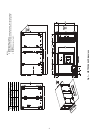
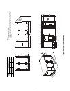
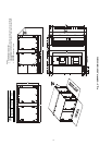
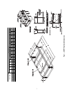
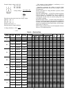
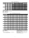
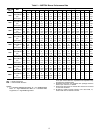
Step 3 — Locate Unit — The following guidelines
should be considered when choosing a location for WSHP. Re-
fer to Fig. 1-3 for unit dimensional data. See Fig. 4 for accesso-
ry roof curb dimensional data.
• Provide sufficient space for water, electrical and duct
connections
• Locate unit in an area that allows for easy access and
removal of filter and access panels
• Allow enough space for service personnel to perform
maintenance
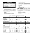
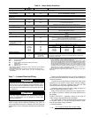
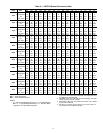
Table 1 — Physical Data — Aquazone™ 50RTP03-20 Units
IPT — Iron (National) Pipe Thread
CAUTION
DO NOT store or install units in corrosive environments or
in locations subject to temperature or humidity extremes
(e.g., attics, garages, rooftops, etc.). Corrosive conditions
and high temperature or humidity can significantly reduce
performance, reliability, and service life. Always move
units in an upright position. Tilting units on their sides may
cause equipment damage.
UNIT 50RTP 03 04 05 06 08 10 12 14 20
Compressor (qty) Scroll (1) Scroll (2)
Factory Charge R-410A (oz) 64 84 120 132 108 120 130 192 300
Blower Motor
Motor Quantity 1
Standard Motor (hp) 1111.523335
Large Motor (hp) N/A 1.5 1.5 2 3 5 5 5 7.5
Blower(s)
Number of Blowers 12
Blower Wheel Size (dia x w) 10 x 6 2 x 12 15 x 11 15 x 15 15 x 11
V-belt size, Std drive A29 A30 A32 AX33 B40 BX42 BX46 B39 BX40
Water Connection Size
IPT (in.)
3
/
4
11
1
/
4
1
1
/
2
2
Coax Volume
Volume (US Gallons) 0.61 0.77 1.11 1.30 1.69 2.29 2.68 3.83 4.77
Condensate Connection Size
FPT (in.) 1
Air Coil Data
Air Coil Total Face Area (sq ft) 5 7 9.33 10.5 20
Filter, Standard, Qty...Size (in.) 4...16 x 20 6...16 x 20
8...16 x 20,
2...20 x 20
Operating Weight (lb) 735 785 835 880 1080 1125 1175 1770 1960
Shipping Weight (lb) 750 800 850 900 1100 1150 1200 1800 2000
Corner Weights (lb)
Front-Left 184 196 208.5 224 292 303.5 320 479 530
Front-Right 259 276 293.5 298 380 395.5 406 623 690
Rear-Left 108.5 117 124.5 134 193 202 212.5 315 350
Rear-Right 183.5 196 208.5 224 215 224 236.5 353 390
Curb, Installed (lb) 83 94 128