30
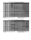
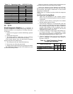
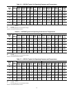
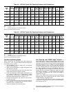
Table 24 — 50PC048 Typical Unit Operating Pressures and Temperatures
LEGEND
*Based on 15% Methanol antifreeze solution.
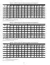
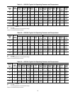
Table 25 — 50PC060 Typical Unit Operating Pressures and Temperatures
LEGEND
*Based on 15% Methanol antifreeze solution.
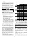
Unit Start-Up Heating Mode
NOTE: Operate the unit in heating cycle after checking the
cooling cycle. Allow 5 minutes between tests for the pressure
or reversing valve to equalize.
1. Turn thermostat to lowest setting and set thermostat
switch to HEAT position.
2. Slowly turn the thermostat to a higher temperature until
the compressor activates.
3. Check for warm air delivery at the unit grille within a few
minutes after the unit has begun to operate.
4. Check the temperature of both supply and discharge wa-
ter. Compare to Tables 15-25. If temperature is within
range, proceed. If temperature is outside the range, check
the heating refrigerant pressures in Tables 15-25.
5. Once the unit has begun to run, check for warm air deliv-
ery at the unit grille.
6. Check air temperature rise across the coil when compres-
sor is operating. Air temperature rise should be between
20 and 30 F after 15 minutes at load.
7. Check for vibration, noise and water leaks.
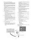
Unit Start-Up with WSHP Open Controls —
The WSHP Open is a multi-protocol (default BACnet*) con-
troller with extensive features, flexible options and powerful
capabilities. The unit comes from the factory pre-programmed
and needs minimal set up to function in a BAS (Building
Automation System) system or provide additional capabilities
to Carrier's WSHP product line. Most settings on the controller
have factory defaults set for ease of installation. There are a
few settings that must be configured in the field and several
settings that can be adjusted if required by unique job condi-
tions. Refer to Appendix A — WSHP Open Screen Configura-
tion. In order to configure the unit, a BACview
6
display is
required. See Fig. 29.
NOTE: If the WSHP Open control has lost its programming,
all display pixels will be displayed on the SPT sensor. See the
WSHP Third Party Integration Guide.
When the unit is OFF, the SPT sensor will indicate OFF.
When power is applied, the SPT sensor will indicate tempera-
ture in the space at 78 F.
ENTERING
WATER
TEMP
(F)
WATER
FLOW
(GPM/ton)
COOLING HEATING
Suction
Pressure
(psig)
Discharge
Pressure
(psig)
Super-
heat
(F)
Sub-
cooling
(F)
Water
Temp
Rise
(F)
Air Temp
Drop
(F) DB
Suction
Pressure
(psig)
Discharge
Pressure
(psig)
Super-
heat
(F)
Sub-
cooling
(F)
Water
Temp
Drop
(F)
Air Temp
Rise
(F) DB
30*
1.5 119-129 190-210 15-20 10-15 19.3-21.3 18-26 63- 73 284-304 5-10 3-8 6.9- 8.9 17-25
2.25 119-129 179-199 15-20 9-14 14.6-16.6 19-27 66- 76 288-308 6-10 3-8 5.0- 7.0 18-26
3 119-129 158-178 15-20 9-14 9.8-11.8 19-27 69- 79 292-312 6-11 3-8 3.1- 5.1 18-26
50
1.5 124-134 248-268 10-15 10-15 19.0-21.0 18-26 92-102 309-329 8-13 3-8 9.5-11.5 23-31
2.25 123-133 230-250 10-15 9-14 14.3-16.3 19-27 96-106 313-333 9-14 3-8 7.0- 9.0 24-32
3 123-133 213-233 10-15 9-14 9.6-11.6 19-27 100-110 317-337 9-14 3-8 4.6- 6.6 24-32
70
1.5 129-139 337-357 8-13 12-17 18.6-20.6 17-25 123-133 339-359 11-16 3-8 12.5-14.5 29-37
2.25 129-139 328-348 8-13 11-16 14.0-16.0 18-26 128-138 344-364 11-16 3-8 9.3-11.3 29-37
3 129-139 300-320 8-13 11-16 9.4-11.4 18-26 133-143 350-370 12-17 3-8 6.2- 8.2 30-38
90
1.5 134-144 426-446 6-11 15-20 18.2-20.2 16-24 153-163 369-389 14-19 1-6 15.4-17.4 33-41
2.25 134-144 406-426 6-11 15-20 13.7-15.7 17-25 160-170 376-396 15-20 1-6 11.6-13.6 35-43
3 134-144 386-406 6-11 15-20 9.2-11.2 17-25 167-177 384-404 16-21 1-6 7.8- 9.8 36-44
110
1.5 140-150 560-580 4- 9 23-28 17.7-19.7 16-24 — — — — — —
2.25 140-150 536-556 4- 9 20-25 13.4-15.4 16-24 — — — — — —
3 139-149 511-531 4- 9 18-22 9.0-11.0 16-24 — — — — — —
DB — Dry Bulb
——No Heating Operation in This Temperature Range
ENTERING
WATER
TEMP
(F)
WATER
FLOW
(GPM/ton)
COOLING HEATING
Suction
Pressure
(psig)
Discharge
Pressure
(psig)
Super-
heat
(F)
Sub-
cooling
(F)
Water
Temp
Rise
(F)
Air Temp
Drop
(F) DB
Suction
Pressure
(psig)
Discharge
Pressure
(psig)
Super-
heat
(F)
Sub-
cooling
(F)
Water
Temp
Drop
(F)
Air Temp
Rise
(F) DB
30*
1.5 108-118 180-200 16-21 10-15 20.6 19-27 61- 71 314-334 6-11 14-19 7.6- 9.6 19-27
2.25 108-118 165-185 16-21 9-14 15.2-17.2 20-28 64- 74 317-337 7-12 13-18 5.6- 7.6 20-28
3 108-118 150-170 16-21 9-14 9.7-11.7 20-28 66- 76 319-339 7-12 13-18 3.6- 5.6 20-28
50
1.5 113-123 206-226 11-14 10-15 19.8-21.8 18-26 90-100 350-370 11-16 14-19 10.5-12.5 25-33
2.25 113-123 190-210 11-14 9-14 14.5-16.5 19-27 95-105 357-377 11-16 14-19 7.9- 9.9 27-35
3 113-123 173-193 11-14 9-14 9.3-11.3 19-27 99-109 364-384 10-15 14-19 5.2- 7.2 28-36
70
1.5 119-129 305-325 9-14 12-17 18.8-20.8 17-25 123-133 391-411 12-17 14-19 13.7-15.7 33-41
2.25 118-128 287-307 9-14 11-14 13.8-15.8 18-26 129-139 399-419 12-17 14-19 10.3-12.3 34-42
3 118-128 269-289 9-14 11-14 8.8-10.8 18-26 135-145 407-427 13-18 14-19 6.9- 8.9 35-43
90
1.5 124-134 402-422 7-12 14-19 17.8-19.8 16-24 157-167 431-451 13-18 13-18 16.8-18.8 38-46
2.25 124-134 382-402 7-12 13-18 13.1-15.1 17-25 164-184 440-460 14-19 13-18 12.7-14.7 39-47
3 123-133 363-383 7-12 13-18 8.3-10.3 17-25 172-182 450-470 16-21 12-17 8.6-10.6 41-49
110
1.5 130-140 500-520 7-12 20-25 17.0-19.0 16-24 — — — — — —
2.25 129-139 479-499 6-11 16-21 12.4-14.4 16-24 — — — — — —
3 128-138 458-478 5-10 13-18 7.8- 9.8 16-24 — — — — — —
DB — Dry Bulb
——No Heating Operation in This Temperature Range
*Sponsored by ASHRAE (American Society of Heating, Refrigerat-
ing and Air Conditioning Engineers).


