


Step 5 — Make Electrical Connections
Unit cabinet must have uninterrupted, unbroken elec-
trical ground to minimize the possibility of personal
injury if an electrical fault should occur. This ground
may consist of electrical wire connected to unit ground
lug in control compartment, or conduit approved for elec-
trical ground when installed in accordance with U.S.A.
National Electrical Code (Ref: ANSI/NFPA 70-1987)
or equivalent local electrical codes. Failure to follow this
warning could result in the installer being liable for per-
sonal injury of others.
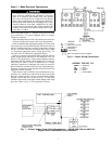
FIELD POWER SUPPLY — Pigtails are provided for field
wire connections. Use factory-supplied splices or copper/
aluminum connector.
When installing units, provide a disconnect per local codes.
All field wiring must comply with local requirements.
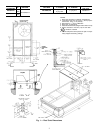
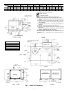
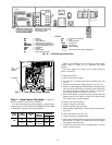
Install conduit through side panel openings. For units with-
out electric heat, install conduit between disconnect and con-
trol box. Install power lines to terminal connections as shown
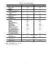
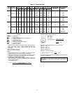
in Fig. 6. For units with electric resistance heat, refer to Table
2 to determine appropriate power wiring figure (Fig.7-13)
and route lines as indicated in appropriate figure.
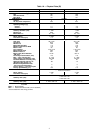
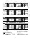
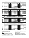
Voltage to compressor terminals during operation must be
within voltage range indicated on unit nameplate (also see
Table 2). On 3-phase units, voltages between phases must be
balanced within 2% and the current within 10%. Use the for-
mula shown in Table 2, Note 3 to determine the % voltage
imbalance. Operation on improper line voltage or excessive
phase imbalance constitutes abuse and may cause damage to
electrical components. Such operation would invalidate any
applicable Carrier warranty.
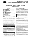
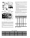
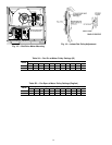
When electric heat is installed, remove knockouts for ap-
propriate size conduit from unit block-off panel and single
point box. Install conduit (rigid or electro-metallic tubing)
through conduit drip boot as shown in Fig. 14. Drip boot
eliminates the need for water tight conduit fittings at the single
point box. Refer to Fig. 15 for component locations.
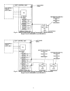
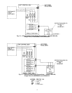
Fig. 7 — Electric Heater Power Wiring Connections — 50LJQ, 220-3-50 and 400-3-50;
Single Point Kit 50DJ902021 and 50DJ902071
LEGEND
C—Contactor
IFC — Indoor-Fan Contactor
TB — Terminal Block
Field Wiring
Factory Wiring
Splice Connection (Factory Supplied)
Fig. 6 — Power Wiring Connections
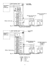
LEGEND FOR FIG. 7-13
EQUIP — Equipment
FU — Fuse
GND — Ground
HTR — Heater
TB — Terminal Block
7