


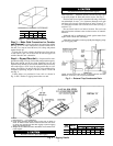
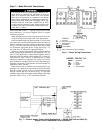
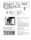
Step 3 — Make Field Connection for Conden-
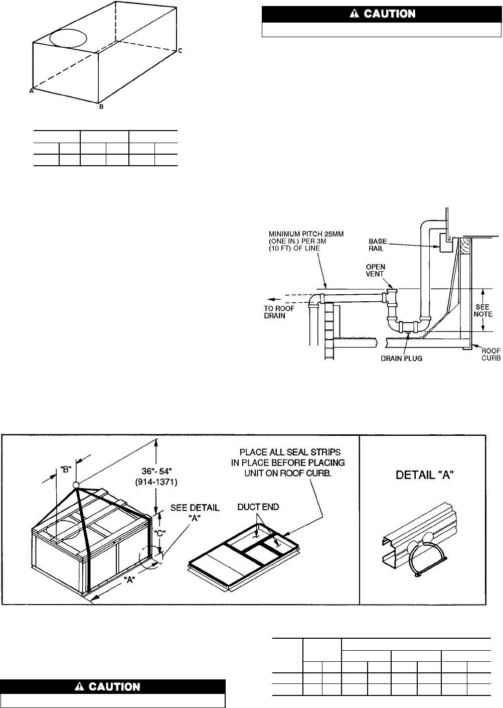
sate Disposal —
Units must have an external trap added.
See Fig. 3. A
3
⁄
4
-in. FPT connection is located on the side of
the unit. Use a trap at least 100 mm (4 in.) deep, and protect
against freeze-up.
If drain line is run to a drain, pitch line away from unit at
25 mm (one in.) per 3 m (10 ft) of run. Do not use a pipe size
smaller than the unit connection.
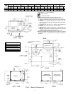
Step 4 — Rig and Place Unit — Inspect unit for trans-
portation damage. File any claim with transportation agency.
Keep unit upright and do not drop. Spreader bars are not
required if top crating is left on unit. Rollers may be used to
move unit across a roof. Level by using unit frame as a ref-
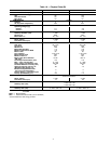
erence. See Tables 1A and 1B and Fig. 4 for additional in-
formation. Operating weight is shown in Tables 1A and 1B
and Fig. 4.
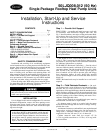
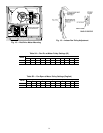
Lifting holes are provided in base rails as shown in
Fig. 4 and 5. Refer to rigging instructions on unit.
All panels must be in place when rigging.
POSITIONING — Maintain clearance around and above unit
to provide proper air flow and service access. See Fig. 5.
Position unit on roof curb so that the following clearances
are maintained; 6 mm (
1
⁄
4
in.) clearance between roof curb
and base rails on each side and front of unit: 29 mm (1
5
⁄
32
in.) clearance between roof curb and rear of unit (see Fig. 1,
section C-C).
Do not install unit in an indoor location. Do not locate
unit air inlet near exhaust vents or other sources of contami-
nated air.
Although unit is weatherproof, guard against water from
higher level runoff and overhangs.
After unit is in position, remove polyethyleneshipping wrap-
per and rigging skid.
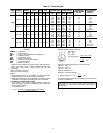
NOTES:
1. Dimensions in ( ) is in millimeters.
2. Hood rigging shackles through holes in base rail, as shown in
detail ‘‘A’’. Holes in base rails are centered around the unit center
of gravity. Use wooden top skid when rigging to prevent rigging
straps from damaging unit.
3. Weights donot includeeconomizer. SeeTables 1Aand1B forecono-
mizer weights.
All panels must be in place when rigging.
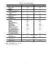
UNIT
50LJQ
MAX
WEIGHT
DIMENSIONS
‘‘A’’ ‘‘B’’ ‘‘C’’
lb kg in. mm in. mm in. mm
008 840 381 87.38 2219 40.25 1022 41.31 1050
012 940 426 87.38 2219 40.25 1022 48.31 1253
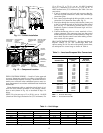
Fig. 4 — Rigging Details
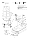
MAXIMUM ALLOWABLE DIFFERENCE
A-B B-C A-C
mm in. mm in. mm in.
13 .5 25 1.0 25 1.0
Fig. 2 — Unit Leveling Tolerance
NOTE: Trap should be deep enough to offset maximum unit static
difference. A 100 mm (4 in.) trap is recommended.
Fig. 3 — External Trap Condensate Drain
3