


Step 6 — Adjust Indoor-Fan Speed — Adjust in-
door fan speed to meet jobsite conditions.
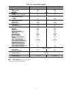
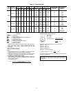
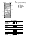
For units with electric resistance heating, required mini-
mum L/s (cfm) is 1062 (2250) for 50LJQ008 and 1416 (3000)
or 50LJQ012, with the following exceptions.
UNIT
50LJQ
UNIT
VOLTAGE
HEATER
kW
UNIT
CONFIG-
URATION
REQUIRED
MINIMUM
L/s Cfm
012
220 50.0
Horizontal
or Vertical
1534 3250
400 50.0
Horizontal
or Vertical
1605 3400
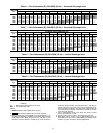
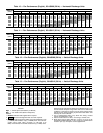
Tables 5A and 5B show fan rps and rpm at motor pulley
settings. Refer to Tables 6-13 to determine fan speed
settings.
Fan motor pulleys are factory set for speed shown in
Tables 1A and 1B.
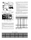
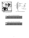
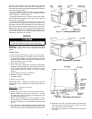
To change fan speed:
a. Shut off unit power supply.
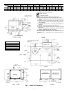
b. Loosen belt by loosening fan motor mounting nuts. See
Fig. 18.
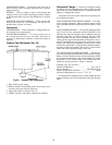
c. Loosen movable pulley flange setscrew (see Fig. 19).
d. Screw movable flange toward fixed flange to increase speed
and away from fixed flange to decrease speed. Increasing
fan speed increases load on motor. Do not exceed maxi-
mum speed specified in Tables 1A and 1B.
e. Set movable flange at nearest keyway of pulley hub and
tighten setscrew (see Tables 1A and 1B for speed change
for each full turn of pulley flange).
To align fan and motor pulleys:
a. Loosen fan pulley setscrews.
b. Slide fan pulley along fan shaft.
c. Make angular alignment by loosening motor from mount-
ing plate.
To adjust belt tension (see Fig. 18):
a. Loosen fan motor mounting bolts.
b. Slide motor mounting plate away from fan scroll for proper
belt tension (13 mm [
1
⁄
2
-in.] deflection with one finger)
and tighten mounting bolts.
c. Adjust bolt and nut on motor mounting plate to secure
motor in fixed position.
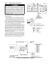
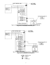
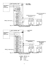
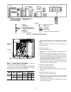
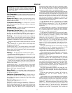
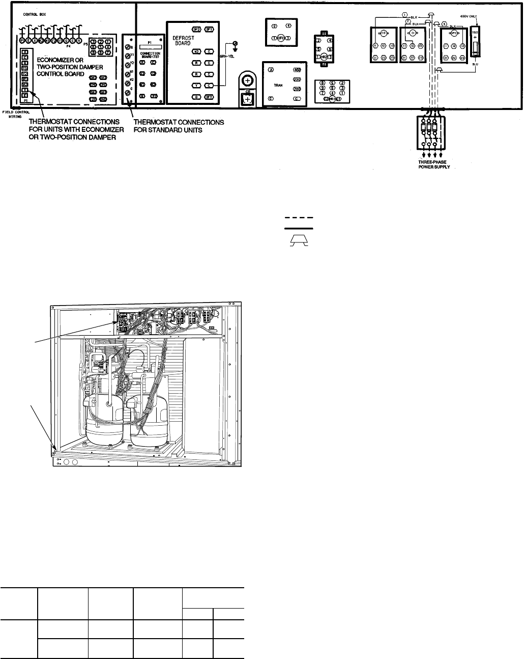
LEGEND
BAT — Battery
C—Contactor
CB — Circuit Breaker
DAT — Discharge-Air Thermistor
EMC/EMFC — Energy Management Closed
EMO/EMFO — Energy Management Open
EQUIP — Equipment
GND — Ground
HR — Heater Relay
IFC — Indoor-Fan Contactor
OFC — Outdoor-Fan Contactor
P—Plug
TB — Terminal Board
TRAN — Transformer
Field Wiring
Factory Wiring
Splice Connection (Factory Supplied)
Fig. 16 — Field Wiring Connections
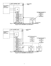
UNIT
CONTROL
BOARD
RACEWAY
Fig. 17 — Field Control Wiring Raceway
13