


FIELD CONTROL WIRING — Install a Carrier-approved
accessory thermostat assembly according to installation in-
structions included with the accessory. Locate thermostat as-
sembly on a solid wall in the conditioned space to sense av-
erage temperature in accordance with thermostat installation
instructions.
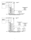
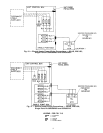
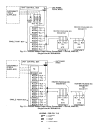
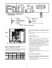
Route thermostat cable or equivalent single leads of col-
ored wire from subbase terminals to low-voltage connec-
tions on unit (shown in Fig. 16) as described in Steps 1-4
below.
NOTE: For wire runs up to 15 m (50 ft), use no. 18 AWG
(American Wire Gage) insulated wire (35 C minimum). For
15 to 23 m (51 to 75 ft), use no. 16 AWG insulated
wire (35 C minimum). For over 23 m (75 ft), use no. 14
AWG insulated wire (35 C minimum). See Table 3 for wire
conversions.
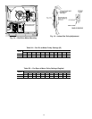
1. If unit is mounted on roof curb and accessory thru-the-
curb service plate connection is used, route wire through
connection plate.
2. Pass control wires through the hole provided on unit (see
connection D, Connection Sizes table, Fig. 5).
3. Feed wire through the raceway built into the corner post
to the 24-v barrier located on the left side of the control
box. See Fig. 17. The raceway provides the UL (U.S.A.
Standard) required clearance between high- and low-
voltage wiring.
4. Connect thermostat wires to screw terminals of low-
voltage connector. The connector plugs into the control
board and may be removed to make connection. Plug con-
nector back into the control board after making connec-
tion or unit will not operate.
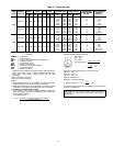
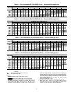
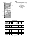
HEATANTICIPATOR SETTINGS — Set first-stage heat an-
ticipator settings at 1.0. Set second-stage heat anti-
cipator settings at 0.6. For units with optional electric heat,
set anticipator for second stage as shown in Table 4.
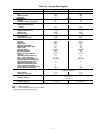
Table 3 — American/European Wire Conversions
AMERICAN EUROPEAN
Industry
Standard Size
American
Conversion
(mm
2
)
Industry
Standard
Size (mm
2
)
18 AWG 0.82 1.0
16 AWG 1.30 1.5
14 AWG 2.08 2.5
12 AWG 3.30 4.0
10 AWG 5.25 6.0
8 AWG 6.36 10.0
6 AWG 13.29 16.0
4 AWG 21.14 25.0
3 AWG 26.65 —
2 AWG 33.61 35.0
1 AWG 42.39 50.0
1/0 AWG 53.49 —
2/0 AWG 67.42 70.0
3/0 AWG 85.00 95.0
4/0 AWG 107.19 120.0
250 kcmil 126.64 150.0
300 kcmil 151.97 —
350 kcmil 177.90 185.0
400 kcmil 202.63 240.0
500 kcmil 253.29 300.0
600 kcmil 303.95 —
LEGEND
AWG — American Wire Gage
kcmil — Thousand Circular Mils
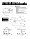
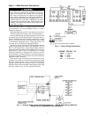
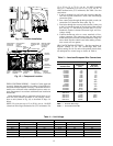
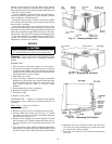
Fig. 14 — Conduit Installation
CONTROL WIRE
TERMINAL
BLOCK
BRACKET AND
CONDUIT DRIP
BOOT
SINGLE POINT
BOX MOUNTING
SCREWS
HEATER
MODULE
(LOCATION 1)
HEATER
MODULE
(LOCATION 2)
HEATER
MOUNTING
BRACKET
HEATER
COVERS
MANUAL RESET
LIMIT SWITCH
LOCATION
(HIDDEN)
HEATER
WIRING
LABEL
CENTER POST
EMT OR RIGID
CONDUIT
(FIELD-
SUPPLIED)
DISCONNECT
MOUNTING
LOCATION
SINGLE
POINT
BOX
MAIN
CONTROL
BOX
Fig. 15 — Component Location
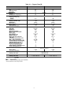
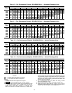
Table 4 — Unit Voltage
220 400
Heater kW Anticipator Setting Part No. 50DJ901— Heater kW Anticipator Setting Part No. 50DJ901—
9.5 0.3 711 10.5 0.3 681
14.6 0.3 601 12.5 0.3 631
22.7 0.6 611 21.0 0.3 641
29.3 0.6 621 25.0 0.3 651
38.8 0.9 711, 621* 31.5 0.6 681, 641*
43.9 0.9 711, 621* 37.5 0.6 631, 651*
*Requires 2 heater packages.
12