


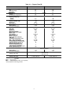
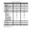
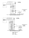
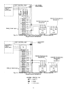
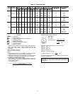
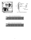
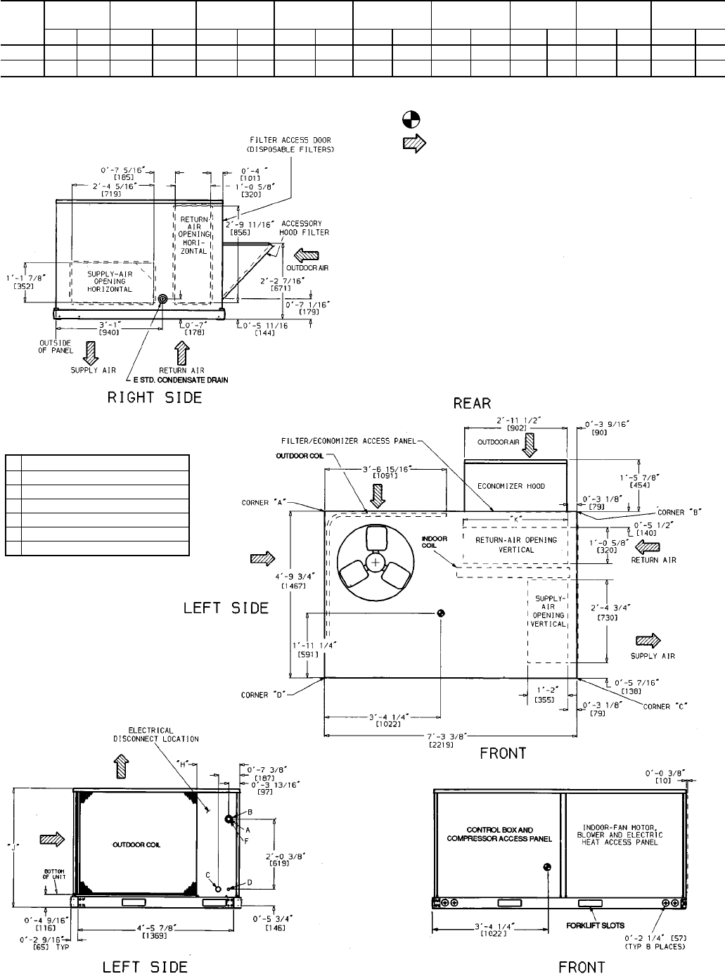
UNIT
50LJQ
STD. UNIT
WEIGHT
ECONOMIZER
WEIGHT
CORNER
WEIGHT ‘‘A’’
CORNER
WEIGHT ‘‘B’’
CORNER
WEIGHT ‘‘C’’
CORNER
WEIGHT ‘‘D’’
‘‘H’’ ‘‘J’’ ‘‘K’’
Lb Kg Lb Kg Lb Kg Lb Kg Lb Kg Lb Kg Ft-in. mm Ft-in. mm Ft-in. mm
008 840 381 44 20 182 83 156 71 231 105 271 123 2-0
7
⁄
8
632 3-5
5
⁄
16
1050 2-9
11
⁄
16
856
012 940 426 44 20 204 93 174 79 259 117 303 137 1-2
7
⁄
8
378 4-1
5
⁄
16
1253 3-0
3
⁄
8
924
CONNECTION SIZES
A 1
3
⁄
8
Љ dia [35] field power supply hole
B 2
1
⁄
2
Љ dia [64] power supply knockout
C 1
3
⁄
4
Љ dia [44] charging-port hole
D
7
⁄
8
Љ dia [22] field control wiring hole
E
3
⁄
4
Љ-14 NPT condensate drain
F 2Љ dia [51] power supply knockout
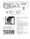
NOTES:
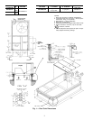
1. Dimensions in [ ] are in millimeters.
2. Center of gravity.
3. Direction of airflow.
4. Ductwork to be attached to accessory roof curb only.
5. Minimum clearance (local codes or jurisdiction may prevail):
a. Bottom to combustible surfaces (when not using curb) 25 mm
(one in.).
b. Condenser coil, for proper airflow, 914 mm (36 in.) one side,
305 mm (12 in.) the other. The side getting the greater clear-
ance is optional.
c. Overhead 1524 mm (60 in.) to assure proper outdoor fan
operation.
d. Between units, control box side, 1067 mm (42 in.).
e. Between unit and ungrounded surfaces, control box side, 914
mm (36 in.).
f. Between unit and block or concrete walls and other grounded
surfaces, control box side 1067 mm (42 in.).
g. Horizontal supply and return end, zero mm (zero in.).
6. With the exception of the clearance for the outdoor coil as stated
in notes 5b and c, a removable fence or barricade requires no
clearance.
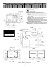
Fig. 5 — Base Unit Dimensions
6