7
Step 4—Rig and Place Unit
Rigging and handling ofthis equipmentcan behazardousformany
reasons due to the installation location (roofs, elevated structures,
etc.).
Only trained, qualified crane operators and ground support staff
should handleand install this equipment.
When working with this equipment, observe precautions in the
literature,ontags,stickers,andlabelsattachedtotheequipment,and
any other safety precautions that might apply.
Training for operators of the lifting equipmentshould include,but
not be limited to, the following:
1. Application of the lifter to the load, and adjustment of the
lifts to adapt to various sizes or kinds of loads.
2. Instruction in any special operation or precaution.
3. Condition of the load as it relates to operation of the lifting
kit, such as balance, temperature, etc.
Follow all applicable safety codes. Wear safety shoes and work
gloves.
INSPECTION
Priortoinitialuse,and atmonthlyintervals, allrigging bracketsa nd
straps should be visually inspected for any damage, evidence of
wear, structural deformation, or cracks. Particular attention should
bepaid to excessive wearat hoist hooking pointsand load support
areas. Brackets or straps showing any kind of wear in these areas
must not be used and should be discarded.
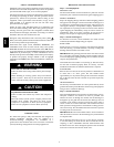
ELECTRICAL SHOCK HAZARD
Failure to follow this warning could result in personal injury
or death.
Before installing or servicing system, always turn off main
power to system. There may be more than one disconnect
switch. Turn of f accessory heater power switch if applicable.
Tag disconnect switch with a suitable warning label.
!
WARNING
UNIT FALLING HAZARD
Failure to follow this warning could result in personal injury
or death.
Never stand beneath rigged units or lift over people.
!
WARNING
INTRODUCTION
The lifting/rigging bracket is engineered and designed to be
installed only on Small Packaged Products. This bracket is to be
used to rig/lift a Small Packaged Product onto roofs or other
elevated structures.
PROPERTY DAMAGE HAZARD
Failure to follow this warning could result in personal
injury/death or property damage.
Rigging brackets for one unit use only. When removing a
unit at the end of its useful life, use a new set of brackets.
!
WARNING
USE OF RIGGING BRACKET
Field Installation of Rigging
Bracket
1. If applicable, remove unit from shipping carton. Leave top
shippingskid ontheunitforuse asaspreaderbartoprevent
the rigging strapsfrom damaging the unit. If the skid is not
available,useaspreaderbarofsufficientlengthto protectthe
unit from damage.
2. Remove 4 screws in unit corner posts.
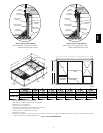
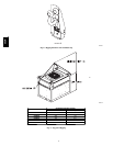
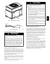
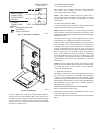
3. Attach each of the 4 metal rigging brackets under the panel
rainlip (SeeFig.8).Usethescrewsremovedinstep2above
to secure the brackets to the unit.
PROPERTY DAMAGE HAZARD
Failure to follow this warning could result in personal
injury/death or property damage.
Rigging bracket MUST be under the rain lip to provide
adequate lifting.
!
WARNING
PROPERTY DAMAGE HAZARD
Failure to follow this warning could result in personal
injury/death or property damage.
Do not strip screws when re--securing the unit. If a screw is
stripped,replacethestrippedonewithalargerdiameterscrew
(included).
!
WARNING
Rigging/Lifting of Unit
1. Bend top of brackets down approximately 30 degreesfrom
the corner posts.
2. Attach straps of equal length to the rigging brackets at
oppositeendsoftheunit.Besurestrapsare rated to holdthe
weight of the unit (See Fig. 9).
3. Attach a clevis of sufficient strength in the middle of the
straps.Adjusttheclevislocation toensureunitisliftedlevel
with the ground.
4. Afterunitissecurelyinplacedetachriggingstraps.Remove
corner posts, screws, and rigging brackets then reinstall
screws.
UNIT FALLING HAZARD
Failure to follow this warning could result in personal
injury/death or property damage.
When straps are taut, the clevis should be a minimum of 36
inches above the unit top cover.
!
WARNING
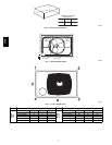
After the unit is placed on the roof curb or mounting pad, remove
the top crating. On 50CR060 unitsonly, 2 wire ties fastened tothe
outdoor coils and reversing valve/accumulator assembly must be
cut. Remove the left and front louvered panels and corner post to
access wire ties. The wire tie to be cut on the left is located
approximately 4 in. down the tube sheet. The wire tie to be cut on
the right is located approximately 6 in. down the tube sheet.
50CR


