


19
Limit Switches
Normally closed limit switch ( LS) completes the control circuit.
Should the leaving--air temperature rise above the maximum
allowable temperature, the limit switch opens and the control
circuit “breaks.” Any interruption in the control circuit instantly
closes the gas valve and stops gas flow to the burners and pilot.
The blower motor continues to run until LS resets.
When the air temperature at the limit switch drops to the
low--temperature setting of the limit switch, the switch closes and
completes the control circuit. The direct--spark ignition system
cycles and the unit returns to normal heating operation.
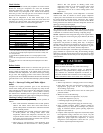
Table 5 – LED Indications
ERROR CODE LED INDICATION
Normal Operation
2
On
Hardware Failure Off
Limit Switch Fault 2 Flashes
Flame Sense Fault 3 Flashes
Four Consecutive Limit Switch Faults 4 Flashes
Ignition Lockout Fault 5 Flashes
Induced--Draft Motor Fault 6 Flashes
Rollout Switch Fault 7 Flashes
Internal Control Fault 8 Flashes
Temporary Lock--Out 1 hr auto reset
1
9 Flashes
NOTES:
1.This code indicates an internal processor fault that will reset itself in one
hr. Fault can be caused by stray RF signals in the structure or n earby. T his
is a UL requirement.
2. LED indicates acceptable operation. Do not change ignition control
board.
3. When W1 is energized the burners will remain on for a minimum of 60
sec.
4.IfmorethanoneerrormodeexiststheywillbedisplayedontheLEDin
sequence.
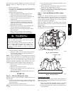
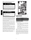
Rollout Switch
The function of the rollout switch is to close the main gas valve in
the event of flame rollout. The switch is located above the main
burners. When the temperature at the rollout switch reaches the
maximum allowable temperature, the control circuit trips, closing
the gas valve and stopping gas flow to the burners. The indoor
(evaporator) fan motor (IFM) and induced draft motor continue to
run until switch is reset. The IGC LED will display FAULT CODE
7.
Step 3 — Start-- up Cooling and Make Adjust-
ments
Complete the required procedures given in the Pre--Start-- Up
section before starting t he unit. Do not jumper any safety devices
when operating the unit. Do not operate the compressor when the
outdoor temperature is below 40°F(4.4°C) (unless accessory
low--ambient kit is installed). Do not rapid--cycle the compressor.
Allow 5 minutes between on cycles to prevent compressor damage.
Checking Cooling Control Operation
Start and check the unit for proper cooling control operation as
follows:
1. Place room th ermostat SYSTEM switch in OFF position.
Observe that blower motor starts when FAN switch is
placed in ON position and shuts down when FAN switch is
placed in AUTO position.
2. Place SYSTEM switch in C OOL position and FAN switch
in AUTO position. Set cooling control below room
temperature. Observe that compressor, condenser fan, and
evaporator blower motors start. Observe that cooling cycle
shuts down when control setting is satisfied. The evaporator
fan will continue to run for 60 sec.
3. When using an auto--changeover room thermostat, place
both SYSTEM and FAN switches in AUTO positions.
Observe that unit operates in Heating mode when
temperature control is set to call for heating (above room
temperature) and operates in Cooling mode when
temperature control is set to call for cooling (below room
temperature).
IMPORTANT: Three--phase, scroll compressors are direction
oriented. Unit must be checked to ensure proper compressor
3--phase power lead orientation. If not corrected within 5 minutes,
the internal protector will shut off the compressor. The 3--phase
power leads to the unit must be reversed to correct rotation. When
turning backwards, the dif ference between compressor s uction and
discharge pressures will be minimal.
Checking and Adjusting Refrigerant Charge
The refrigerant system is fully charged with PuronR (R-- 410A)
refrigerant and is tested and factory sealed. Allow system to operate
a minimum of 15 minutes before checking or adjusting charge.
NOTE: Adjustment of the refrigerant charge is not required unless
the unit is suspected of not having the proper PuronR (R -- 410A)
charge.
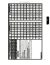
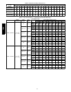
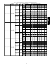
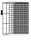
The char ging label and the tables shown refer to system
temperatures and pressures in cooling mode only. A refrigerant
charging label is a ttached to the outside of the service access door.
The chart includes the required liquid line temperature at given
discharge line pressures and outdoor ambient temperatures.
An accurate thermocouple-- or thermistor--type thermometer, and a
gauge manifold are required when using the subcooling charging
method for evaluating the unit charge. Do not use mercury or small
dial--type thermometers because they are not adequate for this type
of measurement.
UNIT DAMAGE HAZARD
Failure to follow this caution may result in unit damage.
When evaluating the refrigerant charge, an indicated
adjustment to the specified factory charge must always be
very minimal. If a substantial adjustment is indicated, an
abnormal condition exists somewhere in the c ooling system,
such as insuf ficient airflow across either coil or both coils.
!
CAUTION
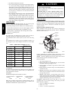
Proceed as follows:
1. Remove caps from low-- and high--pressure service f ittings.
2. Using hoses with valve core depressors, attach low-- and
high--pressure gauge hoses to low-- and high -- pressure
service f ittings, r espectively.
3. Start unit in Cooling Mode and let unit run until system
pressures stabilize.
4. Measure and record the following:
a. Outdoor ambient -- air temperature (°F(°C) db).
b. Liquid line temperature (°F(°C).
c. Discharge (high -- side) pressure (psig).
d. Suction (low--side) pressure (psig) (for reference only).
5. Using “Cooling Charging Charts,” compare outdoor--air
temperature(°F(°C) db) with the discharge line pressure
(psig) to determine desired system operating liquid line
temperature (See Table 7).
6. Compare actual liquid line temperature with desired liquid
line t emperature. Using a tolerance of ± 2°F(±1.1°C), add
refrigerant if actual t emperature is more than 2°F(1.1°C)
higher than proper liquid line temperature, or remove
refrigerant if actual temperature is more than 2°F(1.1°C)
lower than required liquid line temperature.
48ES