


11
Adhere to the following criteria when selecting, sizing, and
installing the duct system:
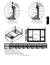
1. Units are shipped for horizontal duct installation (by
removing duct covers).
2. Select and size ductwork, supply-- air registers, and
return--air grilles according to American Society of Heating,
Refrigeration and Air Conditioning Engineers (ASHRAE)
recommendations.
3. Use f lexible transition between rigid ductwork and unit t o
prevent transmission of vibration. The transition may be
screwed or bolted to duct flanges. Use suitable gaskets to
ensure weather--tight and airtight seal.
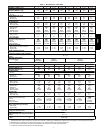
4. All units must have field--supplied f ilters or accessory filter
rack installed in t he return--air side of the unit.
Recommended sizes for filters are shown in Table 1.
5. Size all ductwork for maximum required airflow (either
heating or cooling) for unit being installed. Avoid abrupt
duct size increases or decreases or performance may be
affected.
6. Adequately insulate and weatherproof all ductwork located
outdoors. Insulate ducts passing through unconditioned
space, and use vapor barrier in accordance with latest issue
of Sheet Metal and Air Conditioning Contractors National
Association (SMACNA) and Air Conditioning Contractors
of America (ACCA) minimum installation standards for
heating and air conditioning systems. Secure all ducts to
building structure.
7. Flash, weatherproof, and vibration isolate all openings in
building structure in accordance with local codes and good
building practices.
Step 10 — Install Electrical C onnections
ELECTRICAL SHOCK HAZARD
Failure to follow this warning could result in personal
injury or death.
The unit cabinet must have an uninterrupted, unbroken
electrical ground. This ground may consist of an electrical
wire connected to the unit ground screw in the control
compartment, or conduit approved for electrical ground
when installed in accordance with NFPA 70 (NEC) (latest
edition) (in Canada, Canadian Electrical Code CSA C22.1)
and l ocal electrical codes.
!
WARNING
UNIT COMPONENT DAMAGE HAZARD
Failure to follow this caution may result in damage to the
unit being installed.
1. Ma ke all electrical connections in accordance with NFPA
70 (NEC) (latest edition) and local electrical codes
governing such wiring. In Canada, all electrical
connections must be in accordance with CSA standard
C22.1 Canadian Electrical Code Part 1 and applicable
local codes. Refer to unit wiring diagram.
2. Use only copper conductor for connections between
field--supplied electrical disconnect switch and unit. DO
NOT USE ALUMINUM WIRE.
3. Be sure that high-- voltage power to unit is with in
operating voltage range indicated on unit rating plate. On
3--phase units, ensure phases are balanced within 2
percent. C onsult local power company for correction of
improper voltage and/or phase imbalance.
4. Insulate low-- voltage wires for highest voltage contained
within conduit when low--voltage control wires are in
same conduit as high-- voltage wires.
5. Do not damage internal components when drilling
through any panel to mount electrical hardware, conduit,
etc.
!
CAUTION
High--Voltage Connections
When routing power leads into unit, use only copper wire between
disconnect and unit. The high voltage leads should be in a conduit
until they enter the duct panel; conduit termination at the duct
panel must be watertight.
The unit must have a separate electrical service with a
field--supplied, waterproof disconnect switch mounted at, or within
sight from, the unit. Refer to the unit rating plate, NEC and local
codes for maximum fuse/circuit breaker size and minimum circuit
amps (ampacity) for wire sizing.
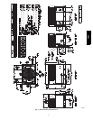
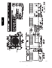
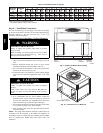
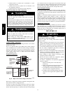
The field-- supplied disconnect switch box may be mounted on the
unit over the high-- voltage inlet hole when the standard power and
low--voltage entry points are used (See Fig. 3 and 4 for acceptable
location).
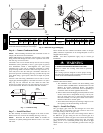
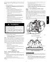
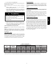
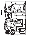
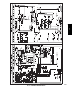
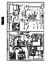
See unit wiring label (Fig. 15, 16 and 17) and Fig. 11 for reference
when making high voltage connections. Proceed as follows to
complete the high--voltage connections to the unit.
Single phase units:
1. Run the high -- voltage (L1, L2) and ground lead into the
control box.
2. Connect ground lead to chassis ground connection.
3. Locate t he black and yellow wires connected to the line side
of the contactor.
4. Connect field L1 to black wire on connection 11 of the
compressor contactor.
5.ConnectfieldwireL2toyellowwireonconnection23of
the compressor contactor.
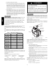
Three--phase units:
1. Run the high--voltage (L1, L2, L3) and ground lead into the
control box.
2. Connect ground lead to chassis ground connection.
3. Locate t he black and yellow wires connected to the line side
of the contactor.
48ES