


10
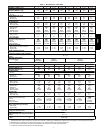
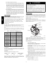
Table 2 – Maximum Gas Flow Capacity*
NOMINAL
IRON PIPE
SIZE (IN.)
INTERNAL
DIAMETER
(IN.)
LENGTH OF PIPE FT (m)†
10
(3)
20
(6)
30
(9)
40
(12)
50
(15)
60
(18)
70
(21)
80
(24)
90
(27)
100
(30)
125
(38)
150
(46)
175
(53)
200
(61)
1/2 .622 175 120 97 82 73 66 61 57 53 50 44 40 — —
3/4 .824 360 250 200 170 151 138 125 118 110 103 93 84 77 72
1 1.049 680 465 375 320 285 260 240 220 205 195 175 160 145 135
1 --- 1/ 4 1.380 1400 950 770 600 580 530 490 460 430 400 360 325 300 280
1 --- 1/ 2 1.610 2100 1460 1180 990 900 810 750 690 650 620 550 500 460 430
*Capacity of pipe in cu ft of gas per hr for gas pressure of 0.5 psig or less. Pressure drop of 0.5---in. wc (based on a 0.60 specific gravity gas). Refer to Table,
National Fire Protection Association NFPA 54.
{ This length includes an ordinary number of fittings.
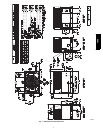
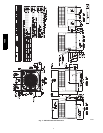
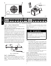
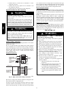
Step 9 — Install Duct Connections
The unit has duct flanges on the supply-- and return-- air openings
on the side and bottom of the unit. For downshot applications, the
ductwork connects to the roof curb (See Fig. 3 and 4 for
connection s izes and locations).
Configuring Units for Downflow (Vertical) Discharge
ELECTRICAL SHOCK HAZARD
Failure to follow this warning could result in personal
injury or death.
Before installing or servicing system, always turn off main
power to system and install lockout tag. There may be
more than one disconnect switch.
!
WARNING
1. Open all electrical disconnects before starting a ny service
work.
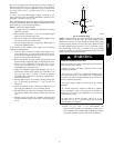
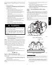
2. Remove horizontal (metal) duct covers to access vertical
(downflow) discharge duct knockouts in unit base.
3. Use a screwdriver and hammer to r emove the panels in the
bottom of the unit base (See Fig. 10).
4. If unit ductwork is to be attached to vertical opening flanges
on the unit base (jackstand applications only), do so at this
time.
PROPERTY DAMAGE HAZARD
Failure to follow this caution may result in property
damage.
Collect ALL screws that were removed. Do not leave
screws on rooftop as permanent damage to the roof may
occur.
CAUTION
!
5. It is recommended that the base insulation around the
perimeter of the vertical return--air opening be secured to
the base with aluminum tape. Applicable local codes may
require aluminum tape to prevent exposed fiberglass.
6. Cover both horizontal duct openings with the provided duct
covers. Ensure opening is air-- and watertight.
7. After completing unit conversion, perform all safety checks
and power up unit.
NOTE: The design and installation of the duct system must be in
accordance with the standards of the NFPA for i nstallation of
nonresidence--type air conditioning and ventilating systems, NFPA
90A or residence--type, NFPA 90B; and/or local codes and
ordinances.
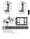
SUPPLY
DUCT
OPENING
RETURN
DUCT
OPENING
VENT HOOD
SHIPPING
LOCATION
A08492
Fig. 9 -- Supply and Return Duct Opening
VERTICAL DUCT COVERS
A08489
Fig. 10 -- Vertical Duct Cover Removed
48ES