


15
4. 112.5 x 1050 = 118,125 Btuh input.
If the desired gas input is 115,000 Btuh, only a minor change in the
manifold pressure is required.
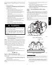
Observe manifold pressure and proceed as follows to adjust gas
input:
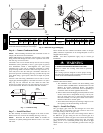
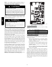
1. Remove regulator cover screw over p lastic adjustment
screw on gas valve (See Fig. 14).
2. Turn plastic adjustment screw clockwise to increase gas
input, or turn plastic adjustment screw counterclockwise to
decrease input (See Fig. 14). Manifold pressure must be
between 3.2 and 3.8 IN. WC.
FIRE AND UNIT DAMAGE HAZARD
Failure to follow this warning could result in personal
injury or death and/or property damage.
Unsafe operation of the unit may result if manifold pressure
is outside this range.
!
WARNING
3. Replace regulator cover screw on gas valve (See Fig. 14).
4. Turn off gas supply to unit. Remove manometer from
pressure tap and replace pipe plug on gas valve. (See Fig.
12.) Turn on gas to unit and check for leaks.
Measure Manifold Pressure (Propane Units)
Refer to propane kit installation instructions for properly checking
gas input.
NOTE: For installations below 2,000 ft (610 m), refer to the unit
rating plate for proper propane conversion kit. For installations
above 2,000 ft (610 m), contact your distributor for proper propane
conversion kit.
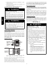
Check Burner Flame
With burner access panel removed, observe the unit heating
operation. Watch the burner flames to see if they are light blue and
soft in appearance, and that the flames are approximately the same
for each burner. Propane will have blue flame (See Fig. 13). Refer
to the Maintenance section for information on burner removal.
Normal Operation
An LED (light--emitting diode) indicator is provided on t he
integrated gas unit controller (IGC) to monitor operation. The IGC
is located by removing the burner access panel. During normal
operation, the LED is continuously on (See Table 5 for error
codes).
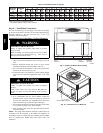
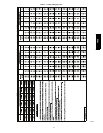
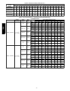
Airflow and Temperature Rise
The heating s ection for each size unit is designed and approved for
heating operation within the temperature--rise range stamped on the
unit rating plate.
Table 9 shows the approved temperature rise range for each heating
input, and the air delivery cfm at various temperature rises for a
given external static pressure. The heating operation airflow must
produce a temperature rise that falls within the approved range.
Refer to Indoor Airflow and Airflow Adjustments section to adjust
heating airflow when required.
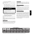
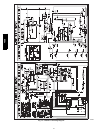
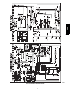
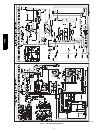
Heating Sequence of Operation
(See Fig. 15--17 and unit wiring label.)
On a call for heating, terminal W of the thermostat is ener gized,
starting the induced--draft motor. When the pressure switch senses
that the induced -- draft motor is moving sufficient combustion air,
the burner sequence begins. This function is performed by the
integrated gas unit controller (IGC). The indoor (evaporator)--fan
motor is energized 45 sec after flame is established. When the
thermostat is satisfied and W is de--ener gized, the burners stop
firing and the indoor (evaporator) fan motor shuts off after a
45--sec time--off delay. Please note that the IGC has the capability
to automatically reduce the indoor fan motor on delay and increase
the indoor fan motor off delay in the event of high duct static
and/or partially-- clogged filter.
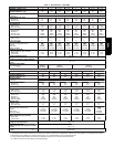
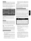
Table 4 – Heating Inputs
HEATING INPUT
(BTUH)
NUMBER
OF
GAS SUPPLY PRESSURE ( IN. W.C.)
MANIFOLD PRESSURE
NUMBER
OF
ORIFICES
Natural{ Propane*{
MANIFOLD
PRES
SURE
(IN. W.C.)
ORIFICES
Min Max Min Max Natural{ Propane*†
40,000 2 4.0 13.0 11.0 13.0 3.2∼3.8 10.0∼11.0
60,000 2 4.0 13.0 11.0 13.0 3.2∼3.8 10.0∼11.0
90,000 3 4.0 13.0 11.0 13.0 3.2∼3.8 10.0∼11.0
115,000 3 4.0 13.0 11.0 13.0 3.2∼3.8 10.0∼11.0
130,000 3 4.0 13.0 11.0 13.0 3.2∼3.8 10.0∼11.0
*When a unit is converted to propane, different size orifices must be used. See separate, natural---to---propane conversion kit instructions.
{Based on altitudes f rom sea level to 2000 ft (610 m) above sea l evel. For altitudes above 2000 ft (610 m), r educe input rating 4 percent for ea ch additional 1000
ft (305 m) above sea level. In Ca nada, from 2000 ft (610 m) above sea l e vel to 4500 ft (1372 m) above sea level, derate th e unit 10 percent.
48ES