


12
4. Connect field L1 to black wire on connection 11 of the
compressor contactor.
5.ConnectfieldwireL3toyellowwireonconnection13of
the compressor contactor.
6. Connect field wire L2 to blue wire from compressor.
Special Procedures for 208--v Operation
ELECTRICAL SHOCK HAZARD
Failure to follow this warning could result in personal
injury or death.
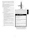
Make sure the power supply to the unit is switched OFF and
install lockout tag. before making any wiring changes. With
disconnect switch open, move black wire from transformer
(3/16 in. [4.8 mm]) terminal marked 230 to terminal marked
208. This retaps transformer to primary voltage of 208 vac.
!
WARNING
ELECTRICAL SHOCK FIRE/EXPLOSION HAZARD
Failure to follow this warning could result in personal
injury or death and property damage.
Before making any wiring changes, make sure the gas
supply is switched off first. Then switch off the power
supply to the unit and install lockout tag.
!
WARNING
Control Voltage Connections
Do not use any type of power--stealing thermostat. Unit control
problems may result.
Use no. 18 American Wire Gage (AWG) color--coded, insulated
(35_C minimum) wires to make the control voltage connections
between the thermostat and the unit. If the thermostat is located
more than 100 ft (30.5 m) from the unit (as measured along the
control voltage wires), use no. 16 AWG color--coded, insulated
(35_C minimum) wires.
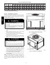
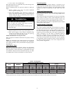
Standard Connection
POWER
SUPPLY
FIELD-SUPPLIED
FUSED DISCONNECT
HIGH VOLTAGE
POWER LEADS
(SEE UNIT WIRING
LABEL
)
EQUIP GR
3-PHASE SHOWN
1-PHASE USES
TWO POWER
LEADS
CONTROL BOX
SPLICE BOX
LOW-VOLTAGE
POWER LEADS
(SEE UNIT
WIRING LABEL)
W
Y
G
R
C
WHT(W1)
YEL(Y)
GRN(G)
RED(R)
BRN(C)
THERMOSTAT
(TYPICAL)
A08205
Fig. 11 -- High-- and Control--Voltage Connections
Run the low-- voltage leads from the thermostat, through the inlet
hole, and into unit low-- voltage splice box.
Locate five 18--gage wires leaving control box. These low--voltage
connection leads can be identified by the colors red, green, yellow,
brown, and white (See Fig. 11). Ensu re the leads are long enough
to be routed into the low--voltage splice box (located below right
side of control box). Route leads through hole in bottom of control
box and make low -- voltage connections (See Fig. 11). Secure all
cut wires, so that they do not interfere with operation of unit.
Heat Anticipator Setting
The room thermostat heat anticipator must be properly adjusted to
ensure proper heating performance. Set the heat anticipator , using
an ammeter between the W and R terminals to determine the exact
required setting.
NOTE: For thermostat selection purposes, use 0.18 amp for the
approximate required setting. Failure to make a proper heat
anticipator adjustment will result in improper operation, discomfort
to the occupants of the conditioned space, and i nef ficient energy
utilization; however, the required setting may be changed slightly
to provide a greater degree of comfort for a particular installation.
Transformer Protection
The transformer is of the energy--limiting type, however a direct
short will likely blow a secondary fuse. If an overload or short is
present, correct overload condition and check for blown fuse on
Indoor Fan board or Integrated Gas Controller. Replace fuse as
required with correct size and rating.
PRE--START--UP
ENVIRONMENTAL, FIRE, EXPLOSION,
ELECTRICAL SHOCK HAZARD
Failure to follow this warning could result in personal
injury or death.
1. Follow recognized safety practices and wear protective
goggles when checking or servicing refrigerant system.
2. Do not operate compressor or provide any electric power
to unit unless compressor plug is in place and secured.
3. Do not remove ccompressor plug until all electrical
sources are disconnected and tagged.
4. Relieve and recover all refrigerant from system before
touching or disturbing compressor plug if refrigerant
leak is suspected around compressor terminals.
5. Never attempt to repair soldered connection while
refrigerant system is under pressure.
6. Do not use torch to remove any component. System
contains oil and refrigerant under pressure.
To remove a component, wear protective goggles and
proceed as follows:
a. Shut off electrical power to unit and install
lockout tag.
b. Relieve and r eclaim all refrigerant from system
using both high-- and low--pressure ports.
c. Cut component connecting tubing with tubing
cutter and remove component from unit.
d. Carefully unsweat remaining tubing stubs when
necessary. Oil can ignite when exposed to torch
flame.
!
WARNING
48ES