


Crankcase Heater — Each compressor has a crankcase heater
to prevent absorption of liquid refrigerant by oil in the crank-
case when the compressor is idle. Since power for the crank-
case heaters is drawn from the unit incoming power, main
unit power must be on for the heaters to be energized.
IMPORTANT: After a prolonged shutdown or serv-
ice job, energize the crankcase heaters for 24 hours
before starting the compressors.
EVAPORATOR FAN MOTOR PROTECTION —A manual
reset, calibrated trip, magnetic circuit breaker protects against
overcurrent. Do not bypass connections or increase the size
of the breaker to correct trouble. Determine the cause and
correct it before resetting the breaker. If the evaporator-fan
motor is replaced with a different horsepower motor, resiz-
ing of the circuit breaker is required. Contact Carrier
Application Engineering.
CONDENSER-FAN MOTOR PROTECTION — Each
condenser-fan motor is internally protected against
overtemperature.
HIGH- AND LOW-PRESSURE SWITCHES — If either
switch trips, or if the compressor overtemperature switch ac-
tivates, that refrigerant circuit will be automatically stopped.
See Compressor Lockout Logic section on this page.
FREEZE PROTECTION THERMOSTAT (FPT) — Freeze
protection thermostats are located on the evaporator coil for
each circuit. One is located at the top and bottom of each
circuit. It detects frost build-up and turns off the compressor,
allowing the coil to clear. Once the frost has melted, the com-
pressor can be reenergized.
Relief Devices — All units have relief devices to pro-
tect against damage from excessive pressures (i.e., fire). These
devices are installed on the suction line, liquid line, and on
the compressor.
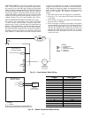
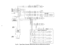
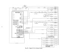
Power Circuit — A typical power wiring schematic is
shown in Fig. 56.
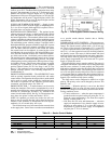
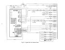
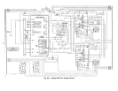
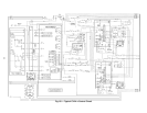
Control Circuit, 115-V — This control circuit is pro-
tected against overcurrent by a 5.0 amp circuit breaker (CB3).
Breaker can be reset. If it trips, determine cause of trouble
before resetting. A typical 115-v control wiring schematic is
shown in Fig. 57 and 58.
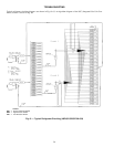
Control Circuit, 24-V — This control circuit is pro-
tected against overcurrent by a 3.2 amp circuit breaker (CB4).
Breaker can be reset. If it trips, determine cause of trouble
before resetting. A typical 24-v control wiring schematic is
shown in Fig. 59 and 60.
Compressor Lockout Logic — If any of the safe-
ties trip, the circuit will automatically reset (providing the
safety has reset) and restart the compressor in 15 minutes. If
any of the safeties trip 3 times within a 90-minute period,
then the circuit will be locked out and will require manual
resetting by turning off either the unit disconnect or the con-
trol circuit breaker, or opening the thermostat.
Replacement Parts — A complete list of replacement
parts may be obtained from any Carrier distributor upon
request.
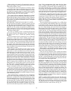
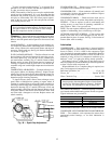
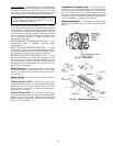
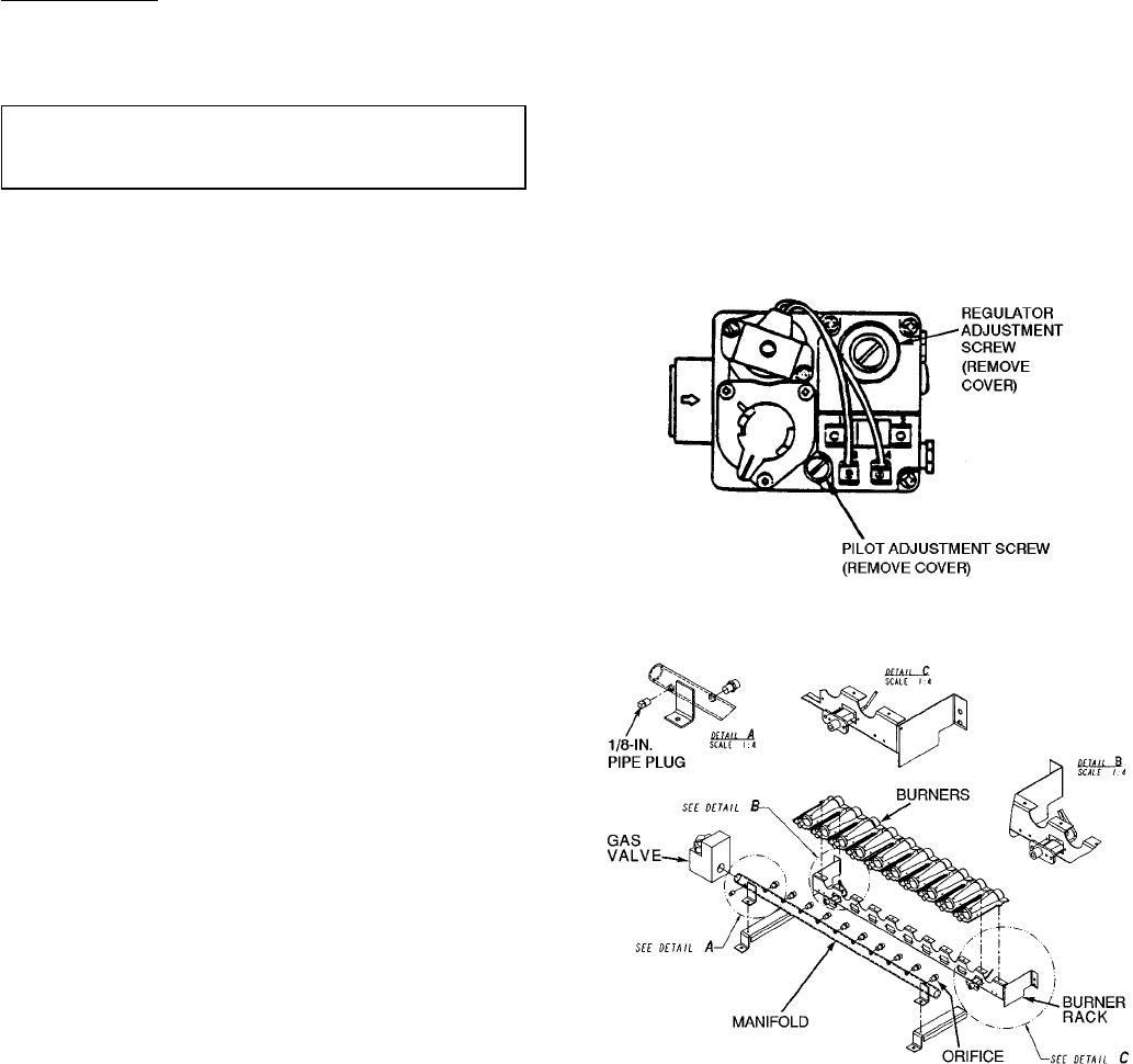
Fig. 54 — Gas Valve
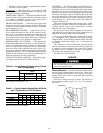
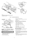
Fig. 55 — Main Burner Removal
49