


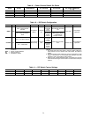
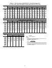
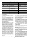

Table 18 — User Defined Set Points
SET POINT
NAME
FORMAT DESCRIPTION LIMITS DEFAULT
OHSP xx.xF Occupied Heat Set Point 55 to 80 F 68 F
OCSP xx.xF Occupied Cool Set Point 55 to 80 F 78 F
UHSP xx.xF Unoccupied Heat Set Point 40 to 80 F 55 F
UCSP xx.xF Unoccupied Cool Set Point 75 to 95 F 90 F
SASP xx.xF Supply Air Set Point 45 to 70 F 55 F
OATL xx.xF Hi OAT Lockout Temperature 55 to 75 F 65 F
NTLO xx.xF Unoccupied OAT Lockout Temperature 40 to 70 F 50 F
RTIO xx.x Reset Ratio 0 to 10 3
LIMT xx.xF Reset Limit 0 to 20° F 10%
MDP xxx% Minimum Damper Position 0 to 100% 20%
LOWMDP xxx%
Low Temperature Minimum
Damper Position Override
0 to 100% 100%
IAQS xxxx IAQ Set Point 1 to 5000 PPM 650 PPM
UHDB xx.xF Unoccupied Heating Deadband 0 to 10° F 1° F
UCDB xx.xF Unoccupied Cooling Deadband 0 to 10° F 1° F
LTMP xxx% Low Temp. Min. Position 0 to 100% 10%
HTMP xxx% High Temp. Min. Position 0 to 100% 35%
PES1 xxx% CV Power Exhaust Stage 1 Point 0 to 100% 25%
PES2 xxx% CV Power Exhaust Stage 2 Point 0 to 100% 75%
LEGEND
CV — Constant Volume
IAQ — Indoor Air Quality
OAT — Outdoor-Air Temperature
If thermostats are used to deenergize the G input, the con-
trol board will turn off indoor fan without any delay and close
economizer dampers.
When cooling, G must be energized before cooling can
operate. The control board determines if outdoor conditions
are suitable for economizer cooling using the standard out-
door air thermistor. For economizer to function for free cool-
ing, the enthalpy must be low, the outdoor air must equal to
or less than the High OutdoorAir Temperature Lockout (de-
fault is 65 F), the SAT (supply-air temperature) thermistor is
NOT in alarm, and outdoor air reading is available. When
these conditions are satisfied, the control boardwill use econo-
mizer as the first stage of cooling.
When Y1 input is energized, the economizer will be modu-
lated to maintain SAT at the defined set point. The default is
55 F. When SAT is above the set point, the economizer will
be 100% open. When SAT is below the set point, the econo-
mizer will modulate between minimum and 100% open po-
sition. When Y2 is energized, the control will turn on com-
pressor no. 1 andcontinue tomodulate economizeras described
above. If the Y2 remains energized and the SAT reading re-
mains above the set point for 15 minutes, compressor no. 2
will turn on. If Y2 is deenergized at any time, only the last
stage of compression that was energized will be turned off.
If outdoor conditions are not suitable for economizer cool-
ing, the economizer will go to minimum position and cycle
compressor no. 1 and 2 based on demand from Y1 and Y2
respectively. The compressors will be locked out when the
SAT temperature is too low (less than 40 F for compressor
no. 1 and less than 45 F for compressor no. 2.) After a com-
pressor is locked out, it can restart after normal time guard
period.
The Time Guard function maintains a minimum off time
of 5 minutes, a minimum ON time of 10 seconds, and a
minimum delay before starting the second compressor of
10 seconds.
When heating, the heat stages respond to the demand from
W1 and W2 of the thermostat input. Heating and cooling
will be mutually locked out on demand on a first call basis.
The heating and the cooling functions cannot be operating
simultaneously.
COOLING, VARIABLE VOLUME UNITS — On power up,
the control module will activate the initialization software
of the control board. The initialization software then reads
DIP switch no. 1 position to determine CV or VAV opera-
tion. Initialization clears all alarms and alerts, re-maps the
input/output database for VAV operation, sets maximum heat
stages to 1 and sets maximum cool stages to 6. The control
reads DIP switch no. 3 and if open, then it sets the internal
flag for expansion mode operation.
The control board will determine if an interface (linkage)
is active and if the unit will operate in a Digital Air Volume
(DAV) mode. In a DAV system, the room terminals are equipped
with microprocessor controls that give commands to the base
unit module. If an interface is active, the control will replace
local comfort set points, space and return air temperatures
and occupancy status with the linkage data supplied.
The control board will determine occupancy status from
Time Schedules (if programmed), Remote Occupied/
Unoccupied input, global occupancy, or DAV. If tempera-
ture compensated start is active, the unit will be controlled
as in the Occupied mode.
NOTE: The temperature compensated start is a period of time
calculated to bring the unit on while unoccupied to reach the
occupied set point when occupancy occurs.
The control board will set the appropriate operating mode
and fan control. The control board will turn VFD on if Oc-
cupied mode is evident.
For units equipped with a start/stop switch only (no space
temperature sensor), if unoccupied and valid return-air tem-
perature reading is available (either from a sensor or DAV),
the control will monitor return-air temperature against Un-
occupied Heat and Cool set points.
For units with a start-stop switch and a space temperature
sensor, the control board will start the VFD whenever SPT
is outside of the set points (Unoccupied Heat or Unoccupied
Cool). The VFD may also be started by nighttime thermostat
via remote Occupied/Unoccupied input or by a temperature
compensated start algorithm. When VFD is running in a nor-
mal mode, the control will start heating or cooling as re-
quired to maintain supply-air temperature at the supply air
set point plus the reset (when enabled). The reset value is
determined by SAT (supply-air temperature) reset and/or space
temperature reset algorithms. The space temperature reset is
only available when enabled through software.
40