


IMPORTANT: THE VAV (variable air volume) units
use variable frequency drives, which generate, use and
can radiate radio frequency energy. If units are not in-
stalled and used in accordance with these instructions,
they may cause radio interference.They have been tested
and found to comply with limits of a Class A com-
puting device as defined by FCC (Federal Communi-
cations Commission) regulations, Subpart J of Part 15,
which are designed to provide reasonable protection
against such interference when operated in a commer-
cial environment.
The unit must be electrically grounded in accordance
with local codes and NEC ANSI/NFPA 70 (National Fire
Protection Association).
Affix crankcase heater sticker (located inthe installers packet)
to unit disconnect switch.
Voltage to compressor terminals during compressor op-
eration must be within the voltage range indicated on the
unit nameplate. On 3-phase units, phases must be balanced
within 2%. Contact local power company for correction of
improper voltage or phase imbalance. Unit failure due to op-
eration of unit on improper line voltage or with excessive
phase imbalance constitutes abuse and may cause damage to
unit electrical components.
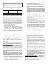
On 208/230-v units, transformer no. 1 is wired for 230-v.
If 208/230-v unit is to be run with 208-v power supply, the
transformer must be rewired as follows:
1. Remove cap from red (208 v) wire.
2. Remove cap from spliced orange (230 v) wire. Discon-
nect orange wire from black unit power wire.
3. Cap orange wire.
4. Splice red wire and black unit power wire. Cap wires.
IMPORTANT: BE CERTAIN UNUSED WIRES
ARE CAPPED. Failure to do so may damage the
transformers.
FIELD CONTROL WIRING — The unit can use either a
Carrier-approved thermostat or a CCN (Carrier Comfort
Network) compatible temperaturesensor. Thermostats are used
on CV (constant volume) units only. Control box diagrams
are shown in Fig. 18 and 19.
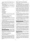
Thermostat Wiring (CV Only) — Install a Carrier-approved
accessory thermostat assembly (per current price pages) ac-
cording to the installation instructions included with the ac-
cessory or these instructions. Locate the thermostat on a solid
interior wall in the conditioned space to sense the average
temperature.
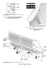
Route the thermostat cable or equivalent single leads of
colored wire from the subbase terminals to the low-voltage
connection as shown on unit label wiring diagram and in
Fig. 20.
NOTE: For wire runs up to 50 ft, use no. 18 AWG
(American Wire Gage) insulated wire (35 C minimum). For
50 to 75 ft, use no. 16 AWG insulated wire (35 C minimum).
For over 75 ft, use no. 14 AWG insulated wire (35 C mini-
mum). All wire larger than no. 18 AWG cannot be directly
connected at the thermostat and will require a junction box
and splice at the thermostat.
Set heat anticipators to 0.1 for all voltages.
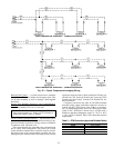
Sensor Wiring (CV or VAV) — The temperature sensor is
wired into the unit control board. See Fig. 21.
The unit is controlled with a T-55 or T-56 (CV only) zone
sensor. Terminal TH (T-56) or T1 (T-55) on the sensor is
connected to T1 of the base module board. Terminal COM
(T-56) or T2 (T-55) on the sensor is connected to T2 on the
base module board. If a T-56 set point override sensor is used,
the override connection SW on the sensor is connected to T3
on the base module board.
If more than sensor is being used and averaged, sensors
must be wired in multiples of 4 or 9. See Fig. 22.
Heat Interlock Relay — VAV units require a field-supplied
heat interlock relay (HIR) to drive the air terminal wide open
when in heat mode. Heat Interlock relay part number is
HN61KK041.
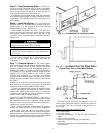
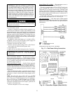
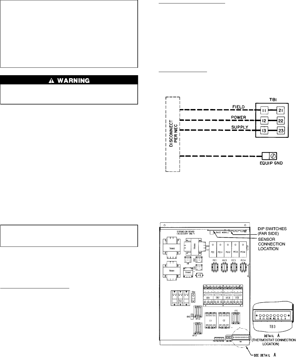
LEGEND
GND — Ground
NEC — National Electrical Code
TB — Terminal Block
NOTE: Maximum wire size for TB1 is 500 MCM.
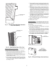
Fig. 17 — Field Power Wiring Connections
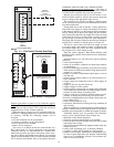
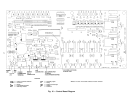
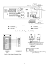
LEGEND
C—Compressor/Contactor
CB — Circuit Breaker
DIP — Dual In-Line Package
FU — Fuse
HR — Heater Relay
IF — Indoor Fan
OF — Outdoor Fan
PEC — Power Exhaust Controller
TB — Terminal Block
TRAN — Transformer
Fig. 18 — Control Box Diagram (Sizes 024-034)
21