


SUBCOOLING METHOD (COOLING, TXV) — To check
and adjust charge during cooling season, use Tables 6A and
6B and the following procedure:
1. Operate unit a minimum of 15 minutes before checking
charge.
2. Measure liquid line temperature near liquid line service
valve, and measure liquid pressure at liquid line service
valve. Use a digital thermometer for all temperature
measurements. DO NOT use mercury or dial-type
thermometers.
3. Refer to Tables 6Aand 6B. Find temperature point at which
the required subcooling temperature intersects the mea-
sured liquid line pressure.
4. If the measured liquid line temperature does not agree
with the required liquid line temperature, ADD refriger-
ant to lower the temperature, or REMOVE refrigerant to
raise the temperature (allow a tolerance of±3F).
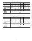
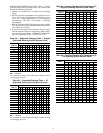
Table 4A — Superheat Charging Table — English
(Superheat Entering Suction Service Valve)
OUTDOOR
TEMP (F)
INDOOR COIL ENTERING AIR (F) WB
50 52 54 56 58 60 62 64 66 68 70 72 74 76
55 9 12141720232629323537404245
60 7 10121518212427303335384043
65 * 6 10 13 16 19 21 24 27 30 33 36 38 41
70 * * 71013161921242730333639
75 * * * 6 9 12 15 18 21 24 28 31 34 37
80 **** 581215182125283135
85 ****** 811151922263033
90 ****** 59131620242731
95 ******* 6101418222529
100 ******** 81215202327
105 ******** 5913172226
110 ********* 611152025
115 ********** 8141823
LEGEND
WB — Wet Bulb
*Do not attempt to charge system under these conditions or refrig-
erant slugging may occur.
Table 4B — Superheat Charging Table — SI
(Superheat Entering Suction Service Valve)
OUTDOOR
TEMP (C)
INDOOR COIL ENTERING AIR (C) WB
10 11 12 13 14 16 17 18 19 20 21 22 23 24
13 5 7 8 9 11 13 14 16 18 19 21 22 23 25
16 4 6 7 8 10 12 13 15 17 18 19 21 22 24
18 * 3679111213151718202123
21 ** 46791112131517182022
24 *** 357810121316171921
27 **** 3478101214161719
29 ****** 4681112141718
32 ****** 357911131517
35 ******* 36810121416
38 ******** 478111315
41 ******** 35791214
43 ********* 3681114
46 ********** 481013
LEGEND
WB — Wet Bulb
*Do not attempt to charge system under these conditions or refrig-
erant slugging may occur.
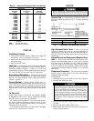
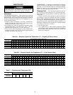
Table 5A — Required Suction-Tube Temperature (F)
— English (Entering Suction Service Valve)
SUPERHEAT
TEMP (F)
SUCTION PRESSURE AT SERVICE PORT (psig)
61.5 64.2 67.1 70.0 73.0 76.0 79.2 82.4 85.7
0 35 36 39 41 43 45 47 49 51
2 37 39 41 43 45 47 49 51 53
4 39 41 43 45 47 49 51 53 55
6 41 43 45 47 49 51 53 55 57
8 43 45 47 49 51 53 55 57 59
10 45 47 49 51 53 55 57 59 61
12 47 49 51 53 55 57 59 61 63
14 49 51 53 55 57 59 61 63 65
16 51 53 55 57 59 61 63 65 67
18 53 55 57 59 61 63 65 67 69
20 55 57 59 61 63 65 67 69 71
22 57 59 61 63 65 67 69 71 73
24 59 61 63 65 67 69 71 73 75
26 61 63 65 67 69 71 73 75 77
28 63 65 67 69 71 73 75 77 79
30 65 67 69 71 73 75 77 79 81
32 67 69 71 73 75 77 79 81 83
34 69 71 73 75 77 79 81 83 85
36 71 73 75 77 79 81 83 85 87
38 73 75 77 79 81 83 85 87 89
40 75 77 79 81 83 85 87 89 91
Table 5B — Required Suction-Tube Temperature (C)
— SI (Entering Suction Service Valve)
OUTDOOR
TEMP (C)
SUCTION PRESSURE AT SERVICE PORT (kPa)
424 443 463 483 503 524 546 568 591
0 2345678911
1 34567891112
2 456789111213
3 5678911121314
4 67891112131415
6 7 8 9 11 12 13 14 15 16
7 8 9 11 12 13 14 15 16 17
8 91112131415161718
9 11 12 13 14 15 16 17 18 19
10 12 13 14 15 16 17 18 19 21
11 13 14 15 16 17 18 19 21 22
12 14 15 16 17 18 19 21 22 23
13 15 16 17 18 19 21 22 23 24
14 16 17 18 19 21 22 23 24 25
16 17 18 19 21 22 23 24 25 26
17 18 19 21 22 23 24 25 26 27
18 19 21 22 23 24 25 26 27 28
19 21 22 23 24 25 26 27 28 29
20 22 23 24 25 26 27 28 29 31
21 23 24 25 26 27 28 29 31 32
22 24 25 26 27 28 29 31 32 33
9