


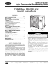
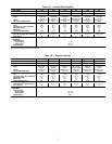
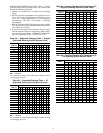
Table 2 — American/European Wire Conversions
AMERICAN EUROPEAN
Industry
Standard
Size
American
Conversion
(mm)
Industry
Standard
Size (mm
2
)
18 AWG 0.82 1.0
16 AWG 1.30 1.5
14 AWG 2.08 2.5
12 AWG 3.30 4.0
10 AWG 5.25 6.0
8AWG 6.36 10.0
6AWG 13.29 16.0
4AWG 21.14 25.0
3AWG 26.65 —
2AWG 33.61 35.0
1AWG 42.39 50.0
1/0 AWG 53.49 —
2/0 AWG 67.42 70.0
3/0 AWG 85.00 95.0
4/0 AWG 107.19 120.0
250 kcmil 126.64 150.0
300 kcmil 151.97 —
350 kcmil 177.90 185.0
400 kcmil 202.63 240.0
500 kcmil 253.29 300.0
600 kcmil 303.95 —
LEGEND
AWG — American Wire Gage
kcmil — Thousand Circular Mils
START-UP
Preliminary Checks
1. Check that all internal wiring connections are tight and
that barriers, covers, and panels are in place.
2. Make certain field electrical power source agrees with unit
nameplate rating.
3. Open all service valves.
Leak Test — Field piping and fan coil must be leak tested
by pressure method described in Carrier Standard Service
Techniques Manual, Chapter 1, Section 1-6. Use R-22 at
approximately 25 psig (172 kPa) backed up with an inert gas
to a total pressure not to exceed 245 psig (1690 kPa).
Evacuate and Dehydrate — Field piping and fan coil
must be evacuated and dehydrated by either of the methods
described in Carrier Standard Service Techniques Manual,
Chapter 1, Section 1-7.
Charge System — Release factory charge into sys-
tem by opening (backseating) liquid and suction line service
valves. Add charge amount as required for the total system.
Refer to separate indoor unit installation instructions for the
required total system charge when connected to the indoor
unit.
To Start Unit
NOTE: When using in conjunction with 40QAB, 40QKB,
or 40QNB fan coils, refer to start-up instructions included
with fan coil for correct start-up procedures.
Be sure that field disconnect is closed. Set room thermo-
stat below ambient temperature. Operate unit for 15 min-
utes, then check system refrigerant charge. See Refrigerant
Charging section on page 8.
Unit compressor starts after a 5-minute delay if equipped
with accessory Time Guard II device.
SERVICE
Before performing recommended maintenance, be
sure unit main power switch is off. Failure to do so may
result in electrical shock or injury from rotating fan blade.
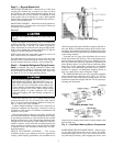
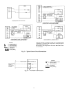
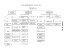
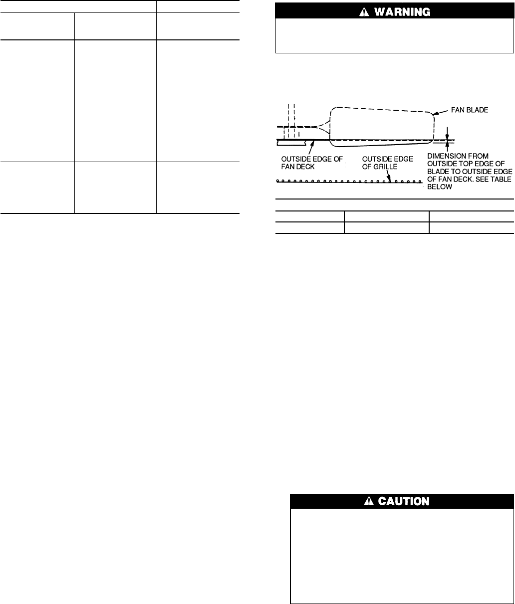
Outdoor Fan — A reinforced wire mount holds the out-
door fan assembly in place. See Fig. 7 for proper mounting
positions.
High-Pressure Relief Valve — Valve is located in
compressor. Relief valve opens at a pressure differential of
approximately 450 ± 50 psig (3100 ± 345 kPa) between suc-
tion (low side) and discharge (high side) to allow pressure
equilization.
Internal Current and Temperature Sensitive Over-
load —
Control resets automatically when internal com-
pressor motor temperature drops to a safe level (overloads
may require up to 45 minutes to reset). When an internal
overload is suspected of being open, check by using an ohm-
meter or continuity tester. If necessary, refer to Carrier Stand-
ard Systems Techniques Manual, Chapter 2, for complete
information.
Pumpdown Procedure — The system may be pumped
down in order to make repairs on low side without losing
complete refrigerant charge.
To pumpdown:
1. Attach pressure gage to suction service valve gage port.
2. Frontseat the liquid line valve.
The 38HDL unit coils hold only the factory-designated
amount of refrigerant. Additional refrigerant may cause
units to relieve pressure through compressor inter-
nal pressure relief valve (indicated by sudden rise
of suction pressure) before suction pressure reaches
5 psig (34 kPa). If this occurs, shut off unit imme-
diately, then frontseat the suction valve and remove
and reclaim excess refrigerant following accepted
practice.
3. Start unit and run until suction pressure reaches 5 psig
(34 kPa).
4. Shut unit off and frontseat suction valve.
5. Depressurize low side of unit and recover refrigerant fol-
lowing accepted practice.
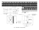
DIMENSIONS — in. (mm)
38HDL018 38HDL024-036 38HDL048-060
0.433 (11) 0.709 (18) 0.16 (4)
Fig. 7 — Condenser Fan Mounting Positions
7