


MAINTENANCE
Before performing recommended maintenance, be sure
unit main power is off. Failure to do so may result in
electrical shock or injury from rotating fan blades.
Lubrication
FAN-MOTOR BEARINGS — Oiling holes are provided at
each end of the condenser-fan motor. Remove fan motor and
lubricate motor with 32 drops (16 drops per hole) of SAE-10
(Society of Automotive Engineers) non-detergent oil at in-
tervals described below:
• Annually, when environment is very dirty, ambient tem-
perature is higher than 105 F (40 C), and average unit op-
erating time exceeds 15 hours a day, or
• Every three years, when environment is reasonably clean,
ambient temperature is less than 105 F (40 C), and unit
operating time averages 8 to 15 hours per day, or
• Every 5 years when environment is clean, ambient tem-
perature is less than 105 F (40 C), and unit operating time
averages less than 8 hours per day.
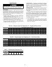
COMPRESSOR — Compressor contains factory oil charges;
replace oil when lost. See Tables 1A and 1B for oil recharge
and refer to Carrier Standard Service Techniques Manual,
Chapter 1, pages 1 to 21 for oil recharging procedure. See
Table 7 for recommended compressor oils.
Cleaning Coils — Coil should be washed out with wa-
ter or blown out with compressed air. Note that the blow-
thru design causes dirt and debris to build up on the inside
of the coils.
Clean coil annually or as required by location and outdoor
air conditions. Inspect coil monthly and clean as required.
Fins are NOT continuous through coil sections. Dirt and de-
bris may pass through the first section, become trapped be-
tween the rows of fins, and restrict condenser airflow. Use a
flashlight to determine if dirt or debris has collected between
coil sections. Clean coil as follows:
1. Turn off unit power.
2. Use a garden hose or other suitable equipment to flush
coil from the outside to remove dirt. Be sure to flush all
dirt and debris from drain holes in the base of unit. Fan
motors are waterproof.
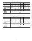
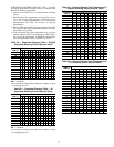
Table 6A — Required Liquid Line Temperature (F) — English (At Service Valve)
REQUIRED
SUBCOOLING (F)
LIQUID PRESSURE AT SERVICE VALVE (PSIG)
134 141 148 156 163 171 179 187 196 205 214 223 233 243 253 264 274 285 297 309 321 331 346 359
0 76 79 82 85 88 91 94 97 100 103 106 109 112 115 118 121 124 127 130 133 136 139 142 145
5 71 74 77 80 83 86 89 92 95 98 101 104 107 110 113 116 119 122 125 128 131 134 137 140
10 66 69 72 75 78 81 84 87 90 93 96 99 102 105 108 111 117 120 123 126 129 129 132 135
15 61 64 67 70 73 76 79 82 85 88 91 94 97 100 103 106 109 112 115 118 121 124 127 130
20 56 59 62 65 68 71 74 77 80 83 86 89 92 95 98 101 104 107 110 113 116 119 122 125
25 51 54 57 60 63 66 69 72 75 78 81 84 87 90 93 96 99 102 105 108 111 114 117 120
Table 6B — Required Liquid Line Temperature (C) — SI (At Service Valve)
REQUIRED
SUBCOOLING (C)
LIQUID PRESSURE AT SERVICE VALVE (PSIG)
911 969 1030 1061 1121 1186 1219 1286 1360 1397 1471 1547 1588 1671 1755 1800 1885 1976 2026 2125 2222 2264 2379 2475
0 24 26 28 29 31 33 34 36 38 39 41 43 44 46 48 49 51 53 54 56 58 59 61 63
2 22 24 26 27 29 31 32 34 36 37 39 41 42 44 46 47 49 51 52 54 56 57 59 61
4 20 22 24 25 27 29 30 32 34 35 37 39 40 42 44 45 47 49 50 52 54 55 57 59
6 18 20 22 23 25 27 28 30 32 33 35 37 38 40 42 43 45 47 48 50 52 53 55 57
8 16 18 20 21 23 25 26 28 30 31 33 35 36 38 40 41 43 45 46 48 50 51 53 55
10 14 16 18 19 21 23 24 26 28 29 31 33 34 36 38 39 41 43 44 46 48 49 51 53
12 12 14 16 17 19 21 22 24 26 27 29 31 32 34 36 37 39 41 42 44 46 47 49 51
14 10 12 14 15 17 19 20 22 24 25 27 29 30 32 34 35 37 39 40 42 44 45 47 49
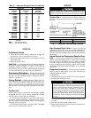
Table 7 — Recommended Compressor Oils
RECOMMENDED
OIL
UNIT 38HDL
018 024 030 036 048 060
3GS
Calumet RO-15
Sontex 200LT •••
•
•
••
10