


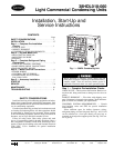
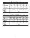
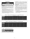
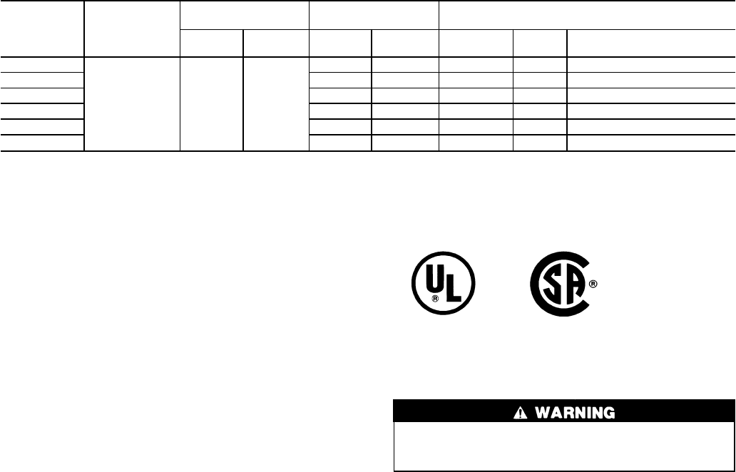
Table 3 — Electrical Data
UNIT SIZE
38HDL
V-PH-Hz
OPERATIONAL
VOLTAGE*
COMPRESSOR POWER SUPPLY
Min Max RLA LRA Fan FLA MCA
Max Fuse† or HACR-Type
Ckt Bkr Amps
018
208/230-1-60 187 254
10.7 47.0 .70 14.1 25
024 13.2 59.0 .70 17.2 30
030 15.7 73.0 .70 20.3 35
036 14.2 86.7 .70 18.5 30
048 24.3 131.0 1.45 31.8 50
060 28.6 170.0 1.45 37.2 65
LEGEND
FLA — Full Load Amps
HACR — Heating, Air Conditioning, Refrigeration
LRA — Locked Rotor Amps
MCA — Minimum Circuit Amps per NEC Section 430-24
NEC — National Electrical Code (U.S.A. Standard)
RLA — Rated Load Amps (Compressor)
*Permissible limits of the voltage range at which unit will operate
satisfactorily.
†Time-delay fuse.
NOTES:
1. Control circuit is 24 v on all units and requires an external power
source.
2. All motors and compressors contain internal overload protection.
3. In compliance with NEC (U.S.A. Standard) requirements for mul-
timotor and combination load equipment (refer to NECArticles 430
and 440), the overcurrent protective device for the unit shall be
fuse or HACR breaker.
4. Motor RLA values are established in accordance with UL (Under-
writers’ Laboratories) Standard 465 (U.S.A. Standard).
Low Pressure Switch — This switch, mounted on the
suction line, has fixed non-adjustable settings. To check pres-
sure switch, attach pressure gage to suction service valve gage
port. Slowly close liquid shutoff valve and allow compres-
sor to pump down. Do not allow compressor to pump down
below 2 psig (14 kPa). Compressor should shut down when
suction pressure drops to cutout pressure in Tables 1A and
1B, and should restart when pressure builds up to cut-in pres-
sure shown after accessory CLO (compressor lockout) switch
has been reset and accessory Time Guard II device has com-
pleted its timing cycle.
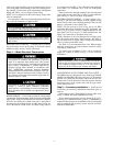
Service Valves — The service valves in the outdoor unit
come from the factory frontseated. This means the refrig-
erant charge is isolated from the line-set connection ports.
To prevent damage to the valve, use a wet cloth or other
acceptable heat sink material on the valve before brazing.
The service valves must be backseated (turned counter-
clockwise until seated) before the service port caps can be
removed and the hoses of the gage manifold connected. In
this position, refrigerant has access from the through out-
door and indoor unit. The service valve cannot be field re-
paired; only a complete valve or valve stem seal and service
port caps are available for replacement.
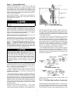
AccuRaterா (Bypass Type) Device — See Fig. 4
for bypass type AccuRater device components. The piston
has a refrigerant metering hole through it. The retainer forms
a stop for the piston in the refrigerant bypass mode and a
sealing surface for liquid line flare connection. To check, clean
or replace piston:
1. Shut off power to unit.
2. Pump down using Pumpdown Procedure section on
page 7.
3. Remove liquid line flare connection from AccuRater
device.
4. Pull retainer out of body, being careful not to scratch flare
sealing surface. If retainer does not pull out easily, care-
fully use locking pliers to remove retainer.
5. Slide piston out by inserting a small soft wire, with small
kinks, through metering hole. Ensure metering hole, seal-
ing surface around piston cones, and fluted portion of pis-
ton are not damaged.
6. Clean piston refrigerant metering hole.
7. Replace retainer O-ring before reassembling AccuRater
device (O-ring part no. 99CC501052).
Refrigerant Charging
To prevent personal injury, wear safety glasses and gloves
when handling refrigerant. Do not overcharge system
— this can cause compressor flooding.
NOTE: Do not vent or depressurize unit refrigerant to atmos-
phere. Remove and reclaim refrigerant following practice.
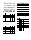
SUPERHEAT METHOD (COOLING, NON-TXV) — To
check and adjust charge during cooling season, use Tables
4A-5B and the following procedure:
1. Operate unit a minimum of 15 minutes before checking
charge.
2. Measure suction pressure by attaching a gage to suction
valve service port.
3. Measure suction line temperature by attaching a service
thermometer to unit suction line near suction valve. In-
sulate thermometer for accurate readings.
4. Measure outdoor coil inlet-air dry bulb temperature with
a second thermometer.
5. Measure indoor coil inlet-air wet bulb temperature with
a sling psychrometer.
6. Refer to Tables 4A and 4B. Find air temperature enter-
ing outdoor coil and wet-bulb temperature entering
indoor coil. At this intersection, note the superheat
temperature.
7. Refer to Tables 5A and 5B. Find superheat temperature
and suction pressure and note suction line temperature.
8. If unit has higher suction line temperature than charted
temperature, add refrigerant until charted temperature,
add refrigerant until charted temperature is reached.
9. If unit has lower suction line temperature than charted
temperature, remove and recover refrigerant until charted
temperature is reached.
10. If air temperature entering outdoor coil or pressure at
suction valve changes, charge to new suction line tem-
perature indicated on chart.
NOTE: The above procedure is independent of indoor air
quantity.
8