


with a wet cloth, the tubing set can be brazed to the service
valve using either silver bearing or non-silver bearing braz-
ing material. Consult local code requirements. Refrigerant
tubing and indoor coil are ready for leak testing.
NOTE: Unit is shipped with R-22 full factory charge indi-
cated on nameplate.
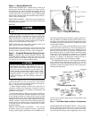
Pass nitrogen or other inert gas through piping while braz-
ing to prevent formation of copper oxide.
To avoid damage while brazing, service valves should
be wrapped in a heat-sinking material such as a wet cloth.
When brazing tubing sets to the service valves, a braz-
ing shield must be used to prevent damage to the painted
unit surface.
PROVIDE SAFETY RELIEF — A fusible plug is located in
unit suction line; do not cap this plug. If local code requires
additional safety devices, install as directed.
Step 4 — Make Electrical Connections
Unit cabinet must have an uninterrupted, unbroken elec-
trical ground to minimize the possibility of personal
injury if an electrical fault should occur. This ground
may consist of electrical wire connected to the unit ground
lug in control compartment, or conduit approved for
electrical ground when installed in accordance with
NEC, ANSI/NFPA (American National Standards
Institute/National Fire Protection Association) 70 (U.S.A.
Standards), and local electrical codes. Failure to follow
this warning could result in the installer being liable for
personal injury to others.
Unit failure as a result of operation on improper line
voltage or excessive phase imbalance constitutes
abuse and may cause damage to electrical components.
Such operation will invalidate any applicable Carrier
warranty.
POWER WIRING — Unit is factory-wired for voltage shown
on nameplate. Provide adequate, fused disconnect switch within
sight of unit, readily accessible but out of reach of children.
Provision for locking the switch open (off) is advisable to
prevent power from being turned on while unit is being ser-
viced. Disconnect switch, fuses, and field wiring must be
in compliance with NEC (U.S.A. Standard) and applicable
local codes. Use minimum 60 C wire for field power
connection.
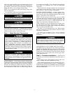
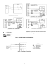
Route power wires through opening in the unit side panel
and connect in unit control box as shown on unit label dia-
gram and Fig. 5 and 6. Unit must be grounded.
CONTROL CIRCUIT WIRING — Control voltage is 24 v.
See Fig. 5 and unit label diagram for field-supplied wiring
details. Route control wire through opening in the unit side
panel to connection in unit control box.
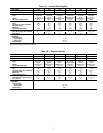
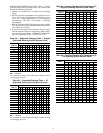
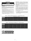
NOTE: For wire runs up to 50 ft (15 m), use no. 18 AWG
(American Wire Gage) insulated wire (35 C minimum). For
50 to 75 ft (15 to 23 m), use no. 16 AWG insulated wire. For
more than 75 ft (23 m), use no. 14 AWG insulated wire. See
Table 2 for conversion to European wire sizes.
NOTE: Operation of unit on improper line voltage consti-
tutes abuse and could affect Carrier warranty. See Table 3.
Do not install unit in system where voltage may fluctuate
above or below permissible limits.
See Table 3 for recommended fuse sizes. When making
electrical connections, provide clearance at unit for refrig-
erant piping connections.
Use indoor unit transformer as 24-v (40-va minimum)
supply for system as shown in Fig. 5 or use accessory
transformer.
Before performing service or maintenance, be sure the
indoor unit main power switch is off and indoor blower
has completely stopped. Failure to do so may result in
electrical shock or injury from rotating fan blades.
CONNECTIONS TO DUCT-FREE FAN COIL UNITS —
The 38HDL units are designed for easy match-up to 40QAB,
40QKB, and 40QNB018,024 duct-free fan coils. These units
provide 24-v power for the outdoor unit from the fan coil.
Connect the Y and C terminals of the indoor unit to the blue
and brown wires of the outdoor unit with 20 gage (mini-
mum) thermostat wire.
Step 5 — Accessory Installation — Install all unit
accessories per accessory installation instructions prior to
start-up.
Do not use accessory Time Guard II device when com-
bining a 38HDL unit with 40QNB indoor units.
When ambient temperature will fall below 55 F (13 C),
accessory low ambient controller (part no. 53DS900060) is
required. When accessory low ambient kit is used, unit should
also be equipped with accessory winter start kit and field-
fabricated wind baffles.
4