


1. Pump system down to 28 in. of mercury and allow pump to
continue operating for an additional 15 minutes.
2. Close service valves and shut off vacuum pump.
3. Connect a nitrogen cylinder and regulator to system and open
until system pressure is 2 psig.
4. Close service valve and allow system to stand for 1 hr. During
this time, dry nitrogen will be able to diffuse throughout the
system absorbing moisture.
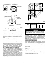
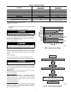
5. Repeat this procedure as indicated in Fig. 10. System will then
be free of any contaminants and water vapor.
FINAL TUBING CHECK
IMPORTANT: Check to be certain factory tubing on both indoor
and outdoor unit has not shifted during shipment. Ensure tubes are
not rubbing against each other or any sheet metal. Pay close
attention to feeder tubes, making sure wire ties on feeder tubes are
secure and tight.
Step 10—Make Electrical Connections
To avoid personal injury or death, do not supply power to unit
with compressor terminal box cover removed.
Be sure field wiring complies with local and national fire, safety,
and electrical codes, and voltage to system is within limits shown
on unit rating plate. Contact local power company to correct
improper voltage. See unit rating plate for recommended circuit
protection device.
NOTE: Operation of unit on improper line voltage constitutes
abuse and could affect unit reliability. See unit rating plate. Do not
install unit in system where voltage or phase imbalance (3-phase)
may fluctuate above or below permissible limits.
NOTE: Use copper wire only between disconnect switch and
unit.
NOTE: Install branch circuit disconnect of adequate size per
NEC to handle unit starting current. Locate disconnect within sight
from and readily accessible from unit, per Section 440-14 of NEC.
ROUTE GROUND AND POWER WIRES
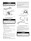
Remove access panel to gain access to unit wiring. Extend wires
from disconnect through power wiring hole provided and into unit
control box.
The unit cabinet must have an uninterrupted or unbroken
ground to minimize personal injury if an electrical fault
should occur. The ground may consist of electrical wire or
metal conduit when installed in accordance with existing
electrical codes. Failure to follow this warning can result in an
electric shock, fire, or death.
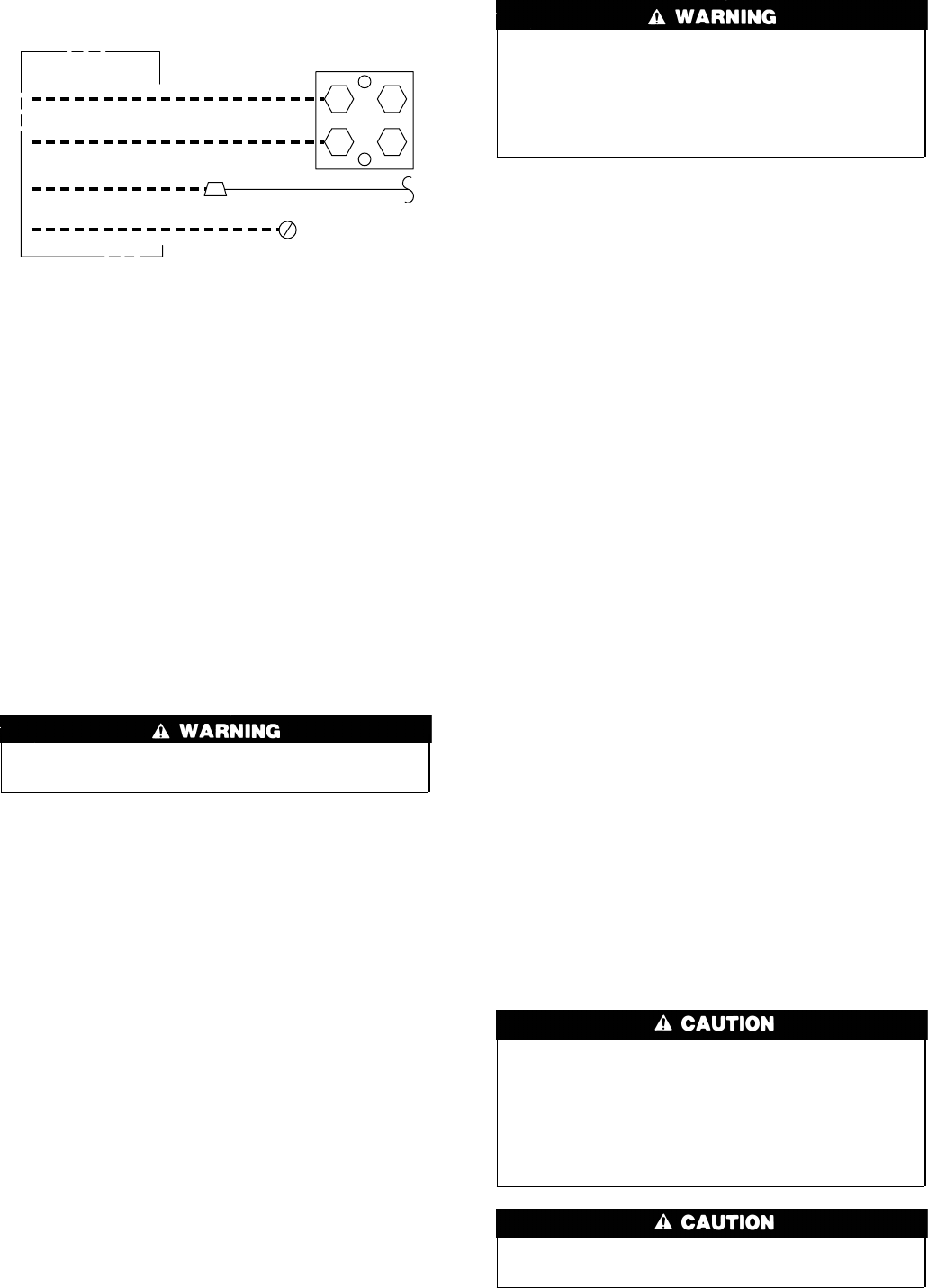
CONNECT GROUND AND POWER WIRES
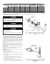
Connect ground wire to ground connection in control box for
safety. Connect power wiring to contactor as shown in Fig. 11.
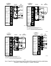
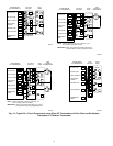
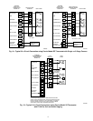
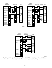
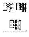
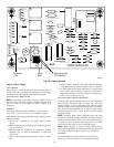
CONNECT CONTROL WIRING
Route 24-v control wires through control wiring grommet and
connect leads to control wiring. (See Fig. 12-17.)
Use No. 18 AWG color-coded, insulated (35°C minimum) wire. If
thermostat is located more than 100 ft from unit, as measured
along the control voltage wires, use No. 16 AWG color-coded wire
to avoid excessive voltage drop.
All wiring must be NEC Class 1 and must be separated from
incoming power leads.
Use furnace transformer, fan coil transformer, or accessory trans-
former for control power, 24-v/40-va minimum.
NOTE: Use of available 24-v accessories may exceed the mini-
mum 40-va power requirement. Determine total transformer load-
ing and increase the transformer capacity or split the load with an
accessory transformer as required.
FINAL WIRING CHECK
IMPORTANT: Check factory wiring and field wire connections
to ensure terminations are secured properly. Check wire routing to
ensure wires are not in contact with tubing, sheet metal, etc.
Step 11—Compressor Crankcase Heater
When equipped with a crankcase heater, furnish power to heater a
minimum of 24 hr before starting unit. To furnish power to heater
only, set thermostat to OFF and close electrical disconnect to
outdoor unit.
A crankcase heater is required in long-line applications (tubing
greater than 50 ft. or elevation greater than 20 ft. between indoor
and outdoor units). Refer to Application Guideline and Service
Manual for Residential Split-System Air Conditioners and Heat
Pumps Using Puron® Refrigerant.
Step 12—Install Electrical Accessories
Refer to the individual instructions packaged with kits or acces-
sories when installing.
Step 13—Start-Up
To prevent compressor damage or personal injury, observe
the following:
• Do not overcharge system with refrigerant.
• Do not operate unit in a vacuum or at negative pressure.
• Do not disable low-pressure switch
In scroll compressor applications:
• Dome temperatures may be hot
To prevent personal injury wear safety glasses, protective
clothing, and gloves when handling refrigerant.
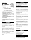
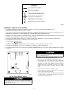
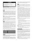
Fig. 11—Line Power Connections
A94025
DISCONNECT
PER N.E.C. AND/OR
LOCAL CODES
CONTACTOR
GROUND
LUG
FIELD GROUND
WIRING
FIELD POWER
WIRING
BLUE
3 PHASE ONLY
6