


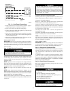
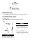

Step 15—Final Checks
IMPORTANT: Before leaving job, be sure to do the following:
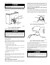
1. Securely fasten all panels and covers.
2. Tighten service valve stem caps to 1/12-turn past finger tight.
3. Leave User’s Manual with owner. Explain system operation
and periodic maintenance requirements outlined in manual.
4. Fill out Dealer Installation Checklist and place in customer
file.
CARE AND MAINTENANCE
For continuing high performance and to minimize possible equip-
ment failure, periodic maintenance must be performed on this
equipment.
Frequency of maintenance may vary depending upon geographic
areas, such as coastal applications.
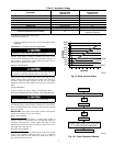
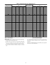
Table 4—Required Liquid-Line Temperature (°F)
LIQUID PRESSURE
AT SERVICE VALVE
REQUIRED SUBCOOLING TEMPERATURE
(°F)
LIQUID PRESSURE
AT SERVICE VALVE
REQUIRED SUBCOOLING TEMPERATURE
(°F)
5 10 15 20 5 10 15 20
174 56 51 46 41 398 112 107 102 97
181 58 53 48 43 405 113 108 103 98
188 61 56 51 46 412 114 109 104 99
195 63 58 53 48 419 115 110 105 100
202 65 60 55 50 426 117 112 107 102
209 67 62 57 52 433 118 113 108 103
216 69 64 59 54 440 119 114 109 104
223 71 66 61 56 447 120 115 110 105
230 73 68 63 58 454 122 117 112 107
237 75 70 65 60 461 123 118 113 108
244 77 72 67 62 468 124 119 114 109
251 79 74 69 64 475 125 120 115 110
258 81 76 71 66 482 126 121 116 111
265 82 77 72 67 489 127 122 117 112
272 84 79 74 69 496 129 124 119 114
279 86 81 76 71 503 130 125 120 115
286 88 83 78 73 510 131 126 121 116
293 89 84 79 74 517 132 127 122 117
300 91 86 81 76 524 133 128 123 118
307 93 88 83 78 531 134 129 124 119
314 94 89 84 79 538 135 130 125 120
321 96 91 86 81 545 136 131 126 121
328 97 92 87 82 552 137 132 127 122
335 99 94 89 84 559 138 133 128 123
342 100 95 90 85 566 139 134 129 124
349 102 97 92 87 573 140 135 130 125
356 103 98 93 88 580 141 136 131 126
363 105 100 95 90 587 142 137 132 127
370 106 101 96 91 594 143 138 133 128
377 107 102 97 92 601 144 139 134 129
384 109 104 99 94 608 145 140 135 130
391 110 105 100 95 — ————
15