


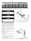
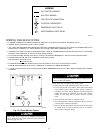

• 3–phase scroll compressors are rotation sensitive.
• A flashing LED on phase monitor indicates reverse rotation.
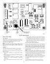
(See Fig. 18 and Table 3.)
• This will not allow contactor to be energized.
• Disconnect power to unit and interchange 2 field wiring
leads on unit contactor.
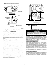
SEQUENCE OF OPERATION
NOTE: Defrost control board is equipped with a 5-minute lock-
out timer which may be initiated upon an interruption of power.
With power supplied to indoor and outdoor units, transformer is
energized.
Cooling
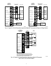
On a call for cooling, thermostat makes circuits R-O, R-Y, and
R-G. Circuit R-O energizes reversing valve, switching it to cooling
position. On three phase models with scroll compressors, the units
are equipped with a phase monitor to detect if the incoming power
is correctly phased for compressor operation. (See Fig. 18 and
Table 3.) If the phasing is correct, circuit R-Y energizes contactor,
starting outdoor fan motor and compressor circuit. R-G energizes
indoor unit blower relay, starting indoor blower motor on high
speed.
NOTE: If the phasing is incorrect, the contactor will not be
energized. To correct the phasing interchange any two of the three
power connections on the field side.
When thermostat is satisfied, contacts open, de-energizing the
contactor and blower relay. Compressor and motors should stop.
NOTE: If indoor unit is equipped with a time-delay relay circuit,
the blower runs an additional 90 sec to increase system efficiency.
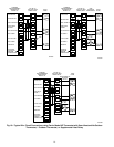
Heating
On a call for heating, thermostat makes circuits R-Y and R-G. If
phasing is correct, circuit R-Y energizes contactor, starting out-
door fan motor and compressor. Circuit R-G energizes indoor
blower relay, starting blower motor on high speed.
Should temperature continue to fall, R-W2 is made through
sec-stage room thermostat bulb. Circuit R-W2 energizes a se-
quencer, bringing on first bank of supplemental electric heat and
providing electrical potential to sec heater sequencer (if used). If
outdoor temperature falls below setting of outdoor thermostat
(field-installed option), contacts close to complete circuit and bring
on sec bank of supplemental electric heat.
When thermostat is satisfied, its contactors open, de-energizing
contactor and sequencer. All heaters and motors should stop.
Quiet Shift
Quiet Shift is a field-selectable defrost mode, which will eliminate
occasional noise that could be heard at the start of the defrost cycle
and restarting of heating cycle. It is selected by placing DIP switch
3 (on defrost board) in ON position.
When Quiet Shift switch is placed in ON position, and a defrost is
initiated, the following sequence of operation will occur. Revers-
ing valve will energize, compressor will turn off for 30 sec, then
turn back on to complete defrost. At the start of heating cycle after
conclusion of defrost mode, reversing valve will de-energize, the
compressor will turn off for another 30 sec, and the fan will turn
off for 40 sec, before starting in the heating mode.
Defrost
The defrost control is a time/temperature control which includes a
field-selectable time period (DIP switch 1 and 2 on the board)
between defrost cycles of 30, 60, 90, or 120 minutes (factory set at
90 minutes).
To initiate a forced defrost, two options are available depending on
the status of the defrost thermostat.
If defrost thermostat is closed, speedup pins (J1) must be shorted
by placing a flat head screwdriver in between for 5 sec and
releasing, to observe a complete defrost cycle. When the Quiet
Shift switch is selected, compressor will be turned off for two 30
sec intervals during this complete defrost cycle as explained
previously. When Quiet Shift switch is in factory default OFF
position, a normal and complete defrost cycle will be observed.
If defrost thermostat is in open position, and speedup pins are
shorted (with a flat head screwdriver) for 5 sec and released, a
short defrost cycle will be observed (actual length is dependent
upon the selected Quiet Shift position). When Quiet Shift switch is
in ON position, the length of defrost is 1 minute (30 sec
compressor off period followed by 30 sec of defrost with com-
pressor operation). On return to heating operation, compressor will
again turn off for an additional 30 sec and the fan for 40 sec. When
the Quiet Shift is in OFF position, only a brief 30 sec cycle will be
observed.
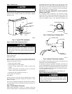
If it is desirable to observe a complete defrost in warmer weather,
the thermostat must be closed as follows:
1. Turn off power to outdoor unit.
2. Disconnect outdoor fan motor lead from OF2 on control board
(See Fig. 19.) Tape to prevent grounding.
3. Restart unit in heating mode, allowing frost to accumulate on
outdoor coil.
4. After a few minutes in heating mode, liquid line temperature
should drop below closing point of defrost thermostat (ap-
proximately 30°F).
NOTE: Unit will remain in defrost until defrost thermostat
reopens at approximately 80°F coil temperature at liquid line or
remainder of defrost cycle time.
5. Turn off power to outdoor and reconnect fan motor lead to
OF2 on control board after above forced defrost cycle.
PressureGuard™ Switch
This outdoor unit is equipped with a heating vapor pressure
limiting device, PressureGuard™, which cycles the outdoor fan at
high ambient heating conditions. The exact ambient at which
outdoor fan cycles depends on indoor and outdoor unit sizing. The
effect of outdoor fan cycling on HSPF (Heating Seasonal Perfor-
mance Factor) is insignificant, due to its occurrence at outdoor
ambients where building load is very low.
Puron® is a high-pressure refrigerant. The purpose of this switch
is to provide maximum flexibility and minimum cost for the
installer/owner by not requiring special thicker wall vapor tubing
and indoor coils, thus allowing limited retrofit. The use of this
switch also allows the maximum number of indoor coil choices at
minimum cost for the installer/owner, since it can use standard
refrigeration tubing.
NOTE: Due to presence of a PressureGuard switch in outdoor
unit fan circuit and the possibility of fan cycling, this unit may go
into brief defrost at high ambient heating conditions.
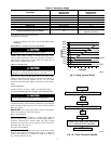
TABLE 3—PHASE MONITOR LED INDICATORS
LED STATUS
OFF No call for compressor operation
FLASHING Reversed phase
ON Normal
13
→
→
→
→