


Step 14—Check Charge
UNIT CHARGE
Factory charge is shown on unit rating plate. To check charge in
cooling mode, refer to Cooling Only Procedure. To check charge
in heating mode, refer to Heating Check Chart Procedure.
COOLING ONLY PROCEDURE
NOTE: If superheat or subcooling charging conditions are not
favorable, charge must be weighed in accordance with unit rating
plate ± 0.6 oz/ft of 3/8-in. liquid line above or below 15 ft
respectively.
EXAMPLE:
To calculate additional charge required for a 25-ft line set:
25 ft - 15 ft = 10 ft X 0.6 oz/ft=6ozofadditional charge
Units installed with cooling mode TXV require charging with the
subcooling method.
1. Operate unit a minimum of 10 minutes before checking
charge.
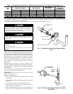
2. Measure liquid service valve pressure by attaching an accurate
gage to service port.
3. Measure liquid line temperature by attaching an accurate
thermistor type or electronic thermometer to liquid near
outdoor coil.
4. Refer to Heat Pump Charging Instructions label on outdoor
unit.
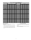
5. Refer to Table 4. Find the point where required subcooling
temperature intersects measured liquid service valve pressure.
6. To obtain required subcooling temperature at a specific liquid
line pressure, add refrigerant if liquid line temperature is
higher than indicated or reclaim refrigerant if temperature is
lower. Allow a tolerance of ± 3°F.
HEATING CHECK CHART PROCEDURE
To check system operation during heating cycle, refer to the HEAT
Pump Charging Instructions label on outdoor unit. This chart
indicates whether a correct relationship exists between system
operating pressure and air temperature entering indoor and outdoor
units. If pressure and temperature do not match on chart, system
refrigerant charge my not be correct. Do not use chart to adjust
refrigerant charge.
NOTE: In heating mode, check refrigerant charge only when
pressures are stable. If operating conditions cause PressureGuard
switch to open and outdoor fan to cycle, check refrigerant charge
in cooling or lower indoor dry bulb temperature. If in doubt,
remove charge and weigh in correct refrigerant charge.
NOTE: When charging is necessary during heating season,
charge must be weighed in accordance with unit rating plate ± 0.6
oz/ft of 3/8-in. liquid line above or below 15 ft respectively.
EXAMPLE:
To calculate additional charge required for a 25-ft line set:
25 ft - 15 ft = 10 ft X 0.6 oz/ft=6ozofadditional charge
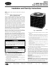
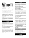
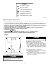
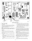
Fig. 19—Defrost Control
A99442
OF2
CESO130076–00
OF1
ON
QUIET
SHIFT
120
30
60
60
30
90
INTERVAL TIMER
OFF
P3
DFT
O R W
2
Y C
T2 C C O
DFT
T1 Y
P1
J1
SPEEDUP
Speedup
Pins
Defrost interval
DIP switches
Quiet
Shift
14