9
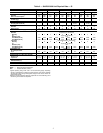
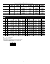
UNIT
STANDARD
WEIGHT, lb (kg)
CENTER OF GRAVITY,
in. (mm)
HEIGHT,
in. (mm)
POWER ENTRY,
in. (mm)
SERVICE VALVE
CONNECTIONS, in. (mm)
X Y H P Suction Liquid
Standard
38APS025 1077 (489) 17.8 (452) 36.9 (937)
61.0 (1549) 24.9 (632)
1
5
/
8
(41)
5
/
8
(16)
38APD025 1095 (497) 17.8 (452) 37.0 (940) 1
3
/
8
(35)
5
/
8
(16)
38APS027 1240 (563) 18.2 (462) 37.6 (955)
73.1 (1857) 36.9 (937)
1
5
/
8
(41)
5
/
8
(16)
38APD027 1258 (571) 18.2 (462) 37.6 (955) 1
3
/
8
(35)
5
/
8
(16)
38APS030 1246 (565) 18.2 (462) 37.5 (953) 1
5
/
8
(41)
7
/
8
(22)
38APD030 1264 (573) 18.2 (462) 37.6 (955) 1
3
/
8
(35)
5
/
8
(16)
Low Sound
38APS025 1113 (505) 17.8 (452) 36.9 (937)
66.5 (1689) 24.9 (632)
1
5
/
8
(41)
5
/
8
(16)
38APD025 1131 (513) 17.8 (452) 37.0 (940) 1
3
/
8
(35)
5
/
8
(16)
38APS027 1276 (579) 18.2 (462) 37.6 (955)
78.6 (1996) 36.9 (937)
1
5
/
8
(41)
5
/
8
(16)
38APD027 1294 (587) 18.2 (462) 37.6 (955) 1
3
/
8
(35)
5
/
8
(16)
38APS030 1282 (582) 18.2 (462) 37.5 (953) 1
5
/
8
(41)
7
/
8
(22)
38APD030 1300 (590) 18.2 (462) 37.6 (955) 1
3
/
8
(35)
5
/
8
(16)
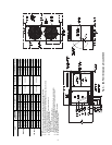
NOTES:
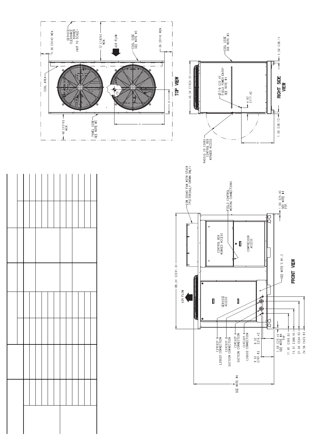
1. Be sure to use a wet rag to remove all valve cores before brazing field piping.
2. Do not cap or otherwise obstruct the liquid line temperature relief.
3. A
7
/
8
in. (22.4 mm) diameter hole is provided for locating field power wiring. Actual hole size
required depends on field wire sizing.
4. A 0.437 in. (11.1 mm) diameter hole is used for mounting unit.
5. Unit must have clearances as follows:
Top - Do not restrict.
Coil End - 72 in. (1829) from solid surface.
Panel Side - 48 in. (1219) per NEC (National Electrical Code, U.S.A. Standard).
6. Unit height dimension for standard and low sound unit with stack fan option.
7. Installation in a pit is not recommended.
8. Unit can be handled using the fork truck lift pockets.
9. Dimensions shown in inches (mm).
a38-7101
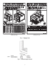
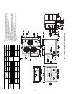
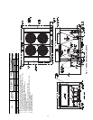
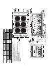
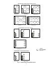
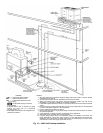
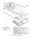
Fig. 5 — 38AP Unit Dimensions, Sizes 025-030


