5
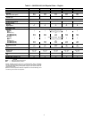
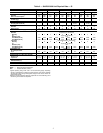
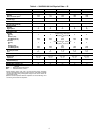
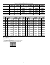
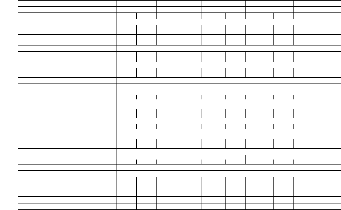
Table 3 — 38AP025-050 Unit Physical Data — SI
LEGEND
*Typical operating charge with 7.62 m of interconnecting piping. Operating
charge is approximate for maximum system capacity. Unit is factory supplied
with nitrogen holding charge. Refrigerant charge for dual circuit units is the
total for both circuits.
†Maximum vertical separation between evaporator coil and condensing unit if
condensing unit is below the evaporator.
38AP UNIT SIZES 025 027 030 040 050
NOMINAL CAPACITY 50/60 Hz (kW) 74/88 81/95 88/106 116/141 148/176
CIRCUIT Dual Single Dual Single Dual Single Dual Single Dual Single
OPERATING WEIGHTS (kg)
Standard 497 489 571 562 573 565 950 893 961 897
With Low Sound Option 513 505 587 579 590 582 974 917 986 921
APPROXIMATE REFRIGERANT CHARGE,
TYPICAL (kg)*
12.7 10.9 13.6 11.8 13.6 11.8 23.6 18.1 23.6 18.1
NITROGEN SHIPPING CHARGE 1.03 bar
COMPRESSOR
kW (Qty) (CKT A/CKT B)
8.2 (2) 8.2 (2) 9.7 (2) 9.7 (2) 11.2 (2) 11.2 (2) 7.5 (2)/
6.3 (2)
9.7 (3) 8.2 (2)/
9.7 (2)
11.2 (3)
CAPACITY STEPS
Standard 222222 4 3 4 3
Digital Option 22 22 22 22 22 22 44 33 44 33
CRANKCASE HEATER (W) (each compressor) 90
CONDENSER FANS
Standard Propeller Type - Direct Drive
Quantity 222222 3 3 3 3
r/s 19 (60 Hz), 16 (50 Hz)
Diameter (mm) 762
Total Watts (60 Hz) 3300 3300 3300 3300 3300 3300 4200 4200 4200 4200
Total Watts (50 Hz) 2750 2750 2750 2750 2750 2750 3500 3500 3500 3500
Low Noise
Shrouded Axial Fan - Direct Drive
Quantity 222222 3 3 3 3
r/s
14 (60 Hz), 12 (50 Hz)
Diameter (mm) 762
Total Watts (60 Hz) 2750 2750 2750 2750 2750 2750 3500 3500 3500 3500
Total Watts (50 Hz) 2300 2300 2300 2300 2300 2300 2900 2900 2900 2900
CONDENSER COIL MCHX Type
No. Coils per Circuit 11
sq m 2.5 2.5 3.2 3.2 3.2 3.2 6.3 6.3 6.3 6.3
TEMPERATURE RELIEF Fusible Plug on Liquid Lines of Each Circuit - 99 C
CONNECTIONS (in.) ODF (CKT A/CKT B)
Suction Line 1
3
/
8
/ 1
3
/
8
1
5
/
8
1
3
/
8
/ 1
3
/
8
1
5
/
8
1
3
/
8
/ 1
3
/
8
1
5
/
8
1
5
/
8
/ 1
5
/
8
2
1
/
8
1
5
/
8
/ 1
5
/
8
2
1
/
8
Liquid Line
5
/
8
/
5
/
8
5
/
8
5
/
8
/
5
/
8
5
/
8
5
/
8
/
5
/
8
7
/
8
5
/
8
/
5
/
8
7
/
8
5
/
8
/
5
/
8
7
/
8
MAXIMUM HEIGHT FOR 1.7° C
SUBCOOLING (m)†
23 23 23 23 23 23 23 23 23 23
CAPACITY PER CIRCUIT (%) (CKT A/CKT B) 50/50 100 50/50 100 50/50 100 54/46 100 48/52 100
MINIMUM UNIT CAPACITY (%) 50 50 50 50 50 50 23 33 23 33
MCHX — Microchannel Heat Exchanger
ODF — Outside Diameter, Female


