


7
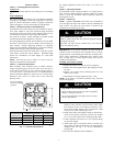
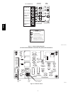
Connect Control W
iring
Route 24v control wires through control wiring grommet and
connect leads to control wiring. See Thermostat Installation
Instructions for wiring specific unit combinations. (See Fig. 9.)
Use No. 18 AWG color-- coded, insulated (35°C minimum) wire.
If thermostat is located more than 100 ft. from unit, as measured
along the control voltage wires, use No. 16 AWG color-- coded
wire to avoid excessive voltage drop.
All wiring must be NEC Class 1 and must be s eparated from
incoming power leads.
Use furnace transformer, fan coil transformer, or accessory
transformer for control power, 24v/40va minimum.
NOTE: Use of available 24v accessories may exceed the
minimum 40va power requirement. Determine total transformer
loading and increase the transformer capacity or split the load
with an accessory transformer as required.
Final Wiring
Check
IMPORTANT: Check factory wiring and field wire connections
to ensure terminations are secured properly. Check wire routing
to ensure wires are not in contact with tubing, sheet metal, etc.
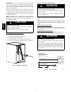
STEP 9 —CompressorCrankcaseHeater
When equipped with a crankcase heater, furnish power to heater a
minimum of 24 hr before starting unit. To furnish power to heater
only, set thermostat to OFF and close electrical disconnect to
outdoor unit.
A crankcase heater is required if refrigerant tubing is longer than
80 ft. Refer to the Long Line Guideline--Residential Split--System
Air Conditioners and Heat Pumps.
STEP 10 —Install Electrical Accessories
Refer to the individual instructions packaged with kits or
accessories when installing.
STEP 11 —Start--Up
CAUTION
!
PERSONAL INJURY HAZARD
Failure to follow this caution may result in personal
injury.
Wear safety glasses, protective clothing, and gloves when
handling refrigerant and observe the following:
S Front seating service valves are equipped with Schrader
valves.
CAUTION
!
ENVIRONMENTAL HAZARD
Failure to follow this caution may result in environmental
damage.
Federal regulations require that you do not vent refrigerant to
the atmosphere. Recover during system repair or final unit
disposal.
CAUTION
!
UNIT OPERATION AND SAFETY HAZARD
Failure to follow this caution may result in minor personal
injury, equipment damage or improper operation.
To prevent compressor damage or personal injury,
observe the following:
S Do not overcharge system with refrigerant.
S Do not operate unit in a vacuum or at negative pressure.
S Do not disable low pressure switch in scroll compressor
applications.
S Dome temperatures may be hot.
Follow these steps to properly start up
system:
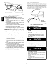
1. After system is evacuated, fully open liquid and vapor
service valves.
2. Unit is shipped with valve stem(s) front seated (closed)
and caps installed. Replace stem caps after system is
opened to refrigerant flow (back seated). Replace caps
finger--tight and tighten with wrench an additional 1/12
turn.
3. Close electrical disconnects to energize system.
4. Set room thermostat at desired temperature. Be sure set
point is below indoor ambient temperature.
5. Set room thermostat to HEAT or COOL and fan control to
ON or AUTO mode, as desired. Operate unit for 15
minutes. Check system refrigerant char ge.
25HCR25HCR