


3
INSTALLATION
STEP 1 —Check Equipment and Job Site
Unpack
Unit
Move to final location. Remove carton taking care not to damage
unit.
Inspect
Equipment
File claim with shipping company prior to installation if shipment
is damaged or incomplete. Locate unit rating plate on unit corner
panel. It contains information needed to properly install unit.
Check rating plate to be sure unit matches job specifications.
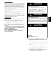
STEP 2 —Install on a Solid, Level Mounting Pad
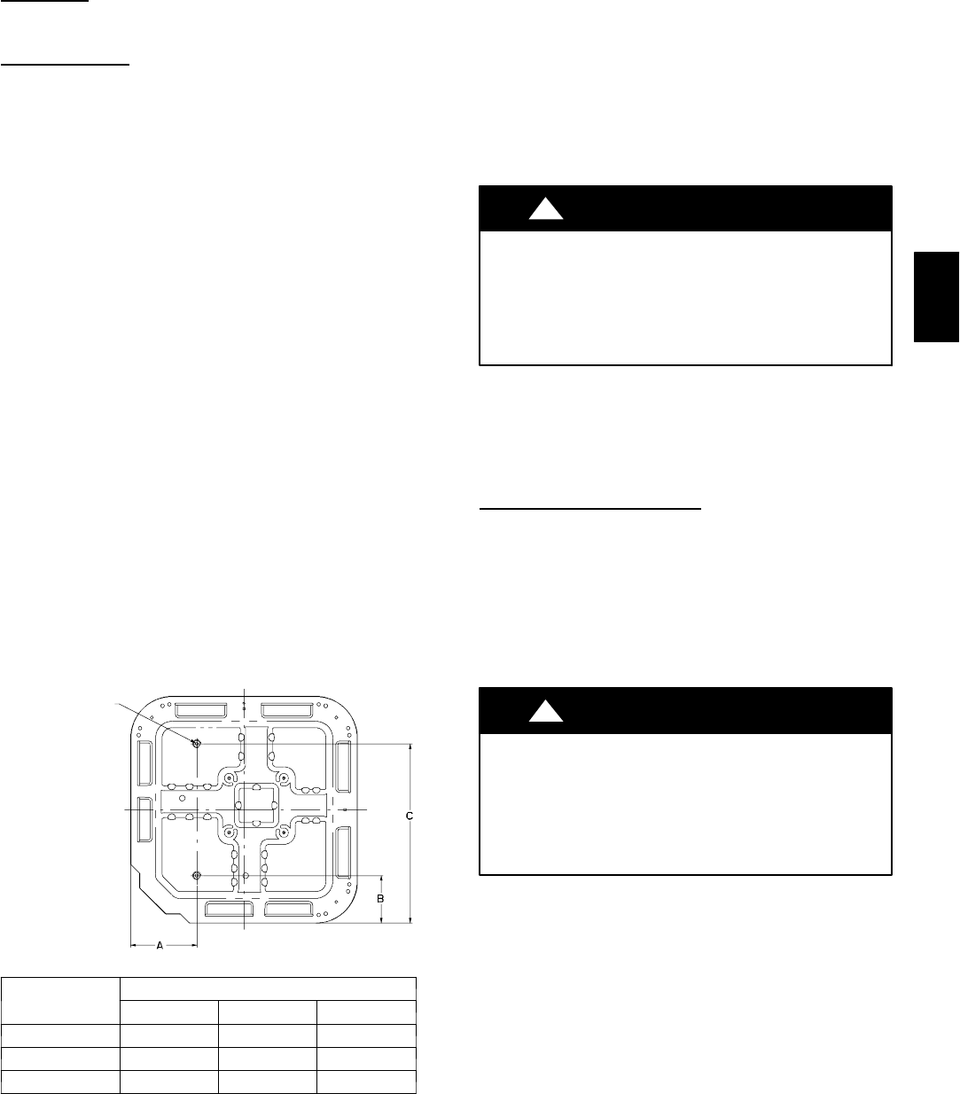
If conditions or local codes require the unit be attached to pad, tie
down bolts should be used and fastened through knockouts
provided in unit base pan. Refer to unit mounting pattern in Fig.
3 to determine base pan size and knockout hole location.
For hurricane tie downs, contact distributor for details and PE
Certification (Professional Engineer), if required.
On rooftop applications, mount on level platform or frame. Place
unit above a load --bearing wall and isolate unit and tubing set
from structure. Arrange supporting members to adequately
support unit and minimize transmission of vibration to building.
Consult local codes governing rooftop applications.
Roof mounted units exposed to winds above 5 mph may require
wind baffles. Consult the Service Manual -- Residential Split
System Air Conditioners and Heat Pumps for wind baffle
construction.
NOTE: Unit must be level to within ± 2° (±3/8 in./ft.) per
compressor manufacturer specifications.
STEP 3 —Clearance Requirements
When installing, allow sufficient space for airflow clearance,
wiring, refrigerant piping, and service. Allow 30 --in. clearance to
service end of unit and 48 in. above unit. For proper airflow, a
6--in. clearance on 1 side of unit and 12 in. on all remaining sides
must be maintained. Maintain a distance of 24 in. between units.
Position so water , snow, or i ce from roof or eaves cannot fall
directly on unit.
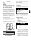
3/8---in. Dia. Tiedown
Knockouts in Basepan
(2) Places
View From Top
UNIT BASE PAN
DIMENSIONS
TIEDOWN KNOCKOUT LOCATIONS
A B C
26 X 26 9–1/8 4–7/16 21–1/4
31–1/2 X31–1/2 9–1/8 6–9/16 24–11/16
35 X 35 9–1/8 6–9/16 28–7/16
A05177
Fig. 3 --- Clearance Requirements
On rooftop applications, locate unit at least 6 in. above roof
surface.
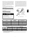
STEP 4 —Operating Ambient
The minimum outdoor operating ambient in cooling mode is
55°F, and the maximum outdoor operating ambient in cooling
mode is 125°F. The maximum outdoor operating ambient in
heating mode is 66 °F.
STEP 5 —Install TXV
NOTE: Applies to non--TXV indoor units only. If installing a
rated and approved indoor coil without a factory installed R--22
TXV, remove and replace the fixed orifice or PuronR TXV
expansion device with an R--22 TXV.
CAUTION
!
UNIT OPERATION HAZARD
Failure to follow this caution may result in equipment damage
or improper operation.
All indoor coil units must be installed with a hard shut off
R--22 TXV metering device.
IMPORTANT: If not factory installed, the TXV should be
mounted as close to the indoor coil as possible and in a vertical,
upright position. Avoid mounting the inlet tube vertically down.
Valve is more susceptible to malfunction due to debris if inlet
tube is facing down. A factory--approved filter drier must be
installed in the liquid line.
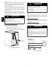
Installing TXV in Place of
Piston
1. Pump system down to 2 psig and recover refrigerant.
2. Remove hex nut from piston body. Use backup wrench on
fan coils.
3. Remove and discard factory--installed piston. Be sure
Teflon seal is in place.
4. Reinstall hex nut. Finger tighten nut plus 1/2 turn.
NOTE: If the piston is not removed from the body, TXV will
not function properly.
CAUTION
!
EQUIPMENT DAMAGE HAZARD
Failure to follow this caution may result in equipment
damage or improper operation.
Use a brazing shield and wrap TXV with wet cloth or
use heat sink material.
5. Install TXV on indoor coil liquid line. Sweat swivel
adapter to inlet of indoor coil and attach to TXV outlet.
Use backup wrench to avoid damage to tubing or valve.
Sweat inlet of TXV, marked “IN” t o liquid line. Avoid
excessive heat which could damage valve.
6. Install vapor elbow with equalizer adapter to suction tube
of line set and suction connection to indoor coil. Adapter
has a 1/4--in. male connector for attaching equalizer tube.
7. Connect equalizer tube of TXV to 1/4--in. equalizer fitting
on vapor line adapter.
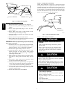
8. Attach TXV bulb to horizontal section of suction line
using clamps provided. Insulate bulb with field--supplied
insulation tape. See Fig. 4 for correct positioning of
sensing bulb.
9. Proceed with remainder of unit installation.
25HCR