


4
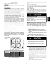
2 O'CLOCK
10 O'CLOCK
SENSING BULB
STRAP
SUCTION TUBE
8 O'CLOCK
4 O'CLOCK
7
⁄
8
IN. OD & SMALLER
LARGER THAN
7
⁄
8
IN. OD
A81032
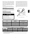
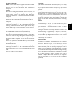
Fig. 4 --- Position of Sensing Bulb
Replacing TXV on Puron Indoor
Coil
1. Pump system down to 2 psig and recover refrigerant.
2. Remove coil access panel and fitting panel from front of
cabinet.
3. Remove TXV support clamp using a 5/16--in. nut driver.
Save the clamp.
4. Remove Puron TXV using a backup wrench on flare
connections to prevent damage to tubing.
5. Using wire cutters, cut equalizer tube off flush with vapor
tube inside cabinet.
6. Remove bulb from vapor tube inside cabinet.
7. Braze equalizer stub--tube closed. Use protective barrier as
necessary to prevent damage to drain pan.
IMPORTANT: Route the equalizer tube of R--22 TXV through
suction line connection opening in fitting panel prior to replacing
fitting panel around tubing.
8. Install TXV with 3/8--in. copper tubing through small hole
in service panel. Use wrench and backup wrench, to avoid
damage to tubing or valve, to attach TXV to distributor.
9. Reinstall TXV support clamp (removed in item 3).
10. Attach TXV bulb to vapor tube inside cabinet, in same
location as original was when removed, using supplied
bulb clamps (nylon or copper). See Fig. 4 for correct
positioning of sensing bulb.
11. Route equalizer tube through suction connection opening
(large hole) in fitting panel and install fitting panel in
place.
12. Sweat inlet of TXV, marked IN to liquid line. Avoid
excessive heat which could damage valve.
13. Install vapor elbow with equalizer adapter to vapor line of
line set and vapor connection to indoor coil. Adapter has
a 1/4--in. male connector for attaching equalizer tube.
14. Connect equalizer tube of TXV to 1/4--in. equalizer fitting
on vapor line adapter. Use backup wrench to prevent
damage to equalizer fitting.
15. Proceed with remainder of unit installation.
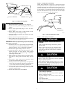
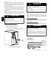
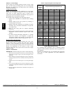
STEP 6 —Check Defrost Thermostat
Check defrost thermostat to ensure it is properly located and
securely attached. There is a liquid header with a brass distributor
and feeder tube going into outdoor coil. At the end of the one of
the feeder tubes, there is a 3/8 in. O.D. stub tube approximately 2
in. long. (See Fig. 5.) The defrost thermostat should be located on
stub tube. Note that there is only one stub tube used with liquid
header, and on most units it is the bottom circuit.
FEEDER TUBE
DEFROST
THERMOSTAT
STUB TUBE
A97517
Fig. 5 --- Defrost Thermostat Location
STEP 7 —Make Piping Connections
!
WARNING
PERSONAL INJURY AND ENVIRONMENTAL
HAZARD
Failure to follow this warning could result in personal
injury or death.
Relieve pressure and recover all refrigerant before
system repair or final unit disposal. Use all service
ports and open all flow--control devices, including
solenoid valves.
CAUTION
!
UNIT DAMAGE HAZARD
Failure to follow this caution may result in equipment
damage or improper operation.
If ANY refrigerant tubing is buried, provide a 6--in. vertical
rise at service valve. Refrigerant tubing lengths up to 36 --in.
may be buried without further special consideration. Do not
bury lines longer than 36 in.
CAUTION
!
UNIT DAMAGE HAZARD
Failure to follow this caution may result in equipment
damage or improper operation.
To prevent damage to unit or service valves, observe the
following:
S Use a brazing shield
S Wrap service valves with wet cloth or use a heat sink
material.
25HCR